CV3100 series and MINI series high performance general purpose inverter instruction manual
3-17
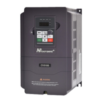
Diagram 3-14 Wiring at communicating PLC with multi inverters
(All the inverters and motors shall be earthed well.)
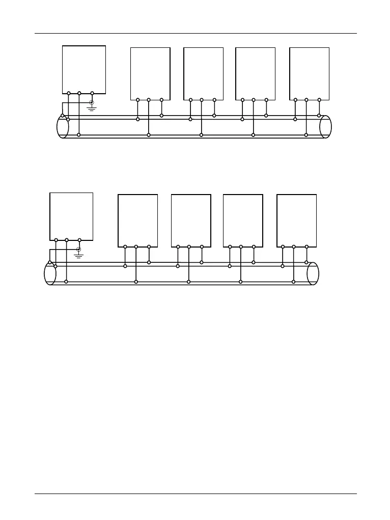
Diagram 3-15 Wiring at communicating among multi inverters
(All the inverter sand motors shall be earthed).
In case that aforementioned wiring can’t provide the normal communication, the
following measures may be tried.
(1) Supply the power for PLC (or upper machine) individually or isolate its power
supply.
(2) Magnetic ring is used on the communicating wire; reduce the carrier frequency of
inverter properly.
CV3100
control plate
of master
 Loading...