86-87050-00 A02 - Page 14
2. Installation
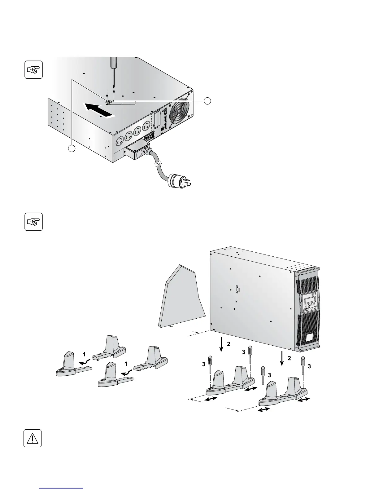
2.2 Internal Battery Connection (Battery Start-up)
BATT. N
O
.
200-25
0V~,
2
4A
RP
O
R
S-232
C
AUTION:
D
O N
O
T
D
IS
C
ONN
E
C
T
B
ATTE
R
Y
CAB
L
E
U
N
DE
R
L
OA
D
B
A
T
TE
R
Y
CO
NN
E
C
TO
R
1
80
V
D
d
c
59
60
Input Cable L6-30P
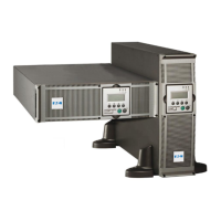
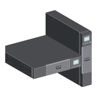
2.3 Installation in Tower Position
Follow steps 1 to 3 in the illustration below to adjust the tower stands for the upright position.
Always keep 6 inches free space behind the UPS rear panel. The distance between the tower stands should
be 17.7 inches.
1. Remove the two mounting screws (59) to
free the battery disconnect switch (60).
2. Push the battery disconnect switch so that
you can read “Connected”.
3. Secure the two mounting screws (59).