86-87050-00 A02 - Page 20
2. Installation
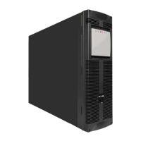
2.8 Connection to Output Receptacles
BATT. N
O
.
200-250V~,
2
4A
RP
O
R
S-232
C
AUTION:
D
O
N
O
T
D
ISC
ON
N
E
C
T
B
AT
TE
R
Y
CAB
L
E
U
N
DE
R
LOA
D
B
A
T
TE
R
Y
CO
N
N
E
C
TO
R
1
80
V
D
d
c
1. Connect the equipment to the UPS 4 NEMA
L6-30R.
If more than one load is connected to the
UPS, the total capacity of the loads should
not exceed 30 Amps.
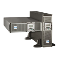
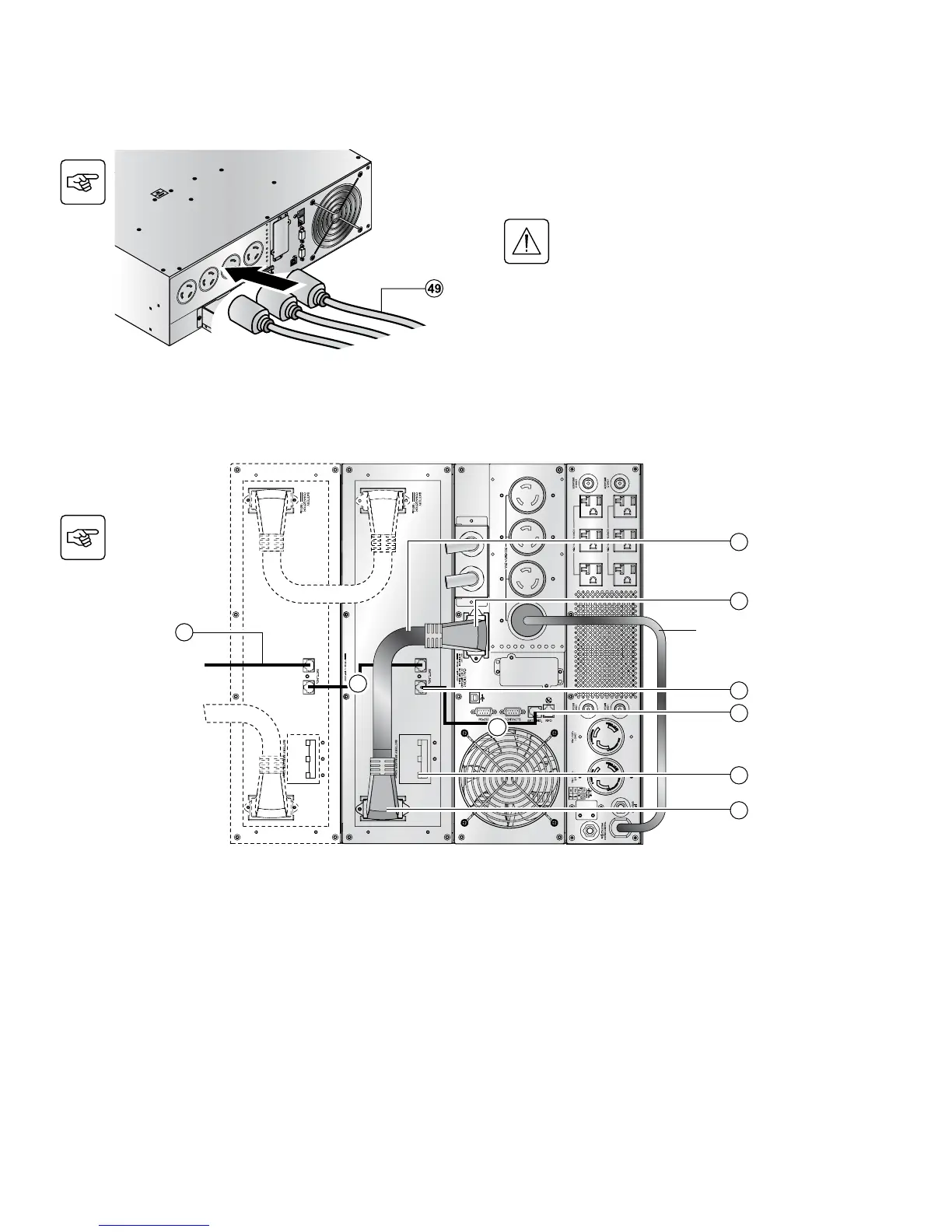
2.9 Connection of Extended Battery Module, UPS, and Transformer
TRANSFORMER
INPUT CABLE
BATTERY
MODULE
BATTERY
MODULE
UPS MODULE
MX
TRANSFORMER
MODULE
12
13
10
11
4
53
53
53
52
1. Check that the battery circuit breaker(s) (13) is OFF («0» position).
2. Connect the battery power cable (52) to the connector (4) of the power module and to the connector (12) of the battery
module.
3. Connect the battery detection cable (53) to the connector (10) of the power module and to the connector (11) of the battery
module.
4. Switch on the battery circuit-breaker(s) (13).