EasyManuals Logo

Eaton C441 Series User Manual

Eaton C441 Series
76 pages
To Next Page IconTo Next Page
To Previous Page IconTo Previous Page
Page #12 background imageLoading...
Page #12 background image
Mounting and Dimensions
C441 PROFIBUS Module User Manual MN042002EN—July 2015 www.eaton.com 5
Mounting and Dimensions
C441Q and C441S
Mounting
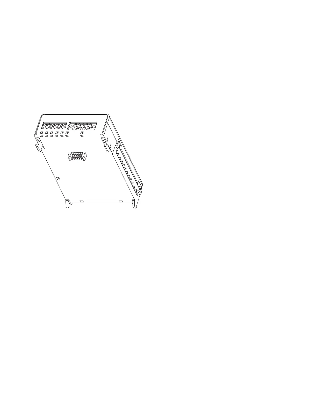
The C441 PROFIBUS adapters are designed to be installed
on the right side of the Motor Insight base unit or the S611.
Figure 1. Installation Diagram
1. Align module with side of Motor Insight base unit or
the S611.
2. Slide module bottom pegs into appropriate slots.
3. Rotate module up and gently click the base unit and
module together.
4. Connect 24 Vdc power, PROFIBUS cable, and IO
connector if desired.
Note: For S611 Soft Starter applications, it is recommended
to mount a C441QS or C441SS module beside the
S611 and wire the D0/D1 terminals between the two
devices. More information on this is provided later in
this document.

Table of Contents

Questions and Answers:

Question and Answer IconNeed help?

Do you have a question about the Eaton C441 Series and is the answer not in the manual?

Eaton C441 Series Specifications

General IconGeneral
SeriesC441
CategoryController
TypeElectronic Overload Relay
Voltage24-240V AC/DC
MountingDIN Rail
Phase Sensitivity3-Phase
Input Voltage24-240V AC/DC
Number of Outputs2
Protection RatingIP20
Reset TypeManual/Automatic
Trip Class10
Auxiliary Contacts1NO+1NC
Communication ProtocolModbus RTU
Operating Temperature-20°C to 60°C
DimensionsVaries by model

Related product manuals