Connections and Switch Settings
C441 PROFIBUS Module User Manual MN042002EN—July 2015 www.eaton.com 13
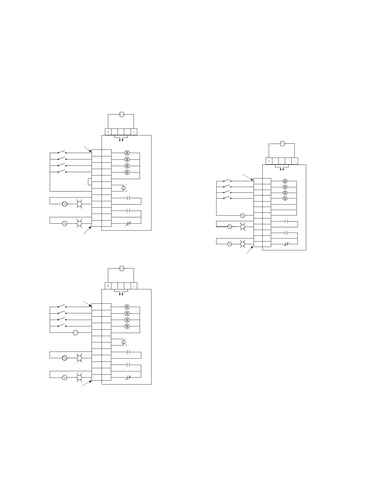
Power and I/O Wiring Diagrams for the
C441QS and C441SS Modules
The C441QS module contains four 24 Vdc inputs and two
relay outputs. The two relay outputs provided are one
form A (NO) and one form C (NO, NC).
Figure 11. C441QS—24 Vdc Input Specification
24 Vdc Inputs
The 24 Vdc input circuit is capable of both isolated and
unisolated behavior. The isolated inputs share a single
common tie point. A 24 Vdc current limited source/ground is
provided in the situations that require locally supplied input
signal voltage. To use the unisolated inputs, tie the 24 Vdc
ground/common to the isolated common.
The C441SS module contains four 120 Vac inputs and two
relay outputs. The two relay outputs provided are one
form A (NO) and one form C (NO, NC).
Figure 12. C441SS—120 Vac Input Specification
D0 D1
To C440, S611
or S811+
D0 D1
To C440, S611
or S811+
Example: Non-isolating
24 Vdc input source
- Input source power is taken
from 5-pin connector
- Connect C and OV together
- Use 24 to source inputs
24 Vdc
24 Vdc
I/O power
Pin 1
Pin 12
AC/DC
AC/DC
I1
I2
I3
I4
C
OV
24
NO
NO
NO
C
NC
I1
I2
I3
I4
C
–
+
Q1
Q1
Q2
C
Q2
Example: Isolated 24 Vdc input source
- The inputs must be supplied
by an external power source
- Do not connect the external
supply to terminals OV and 24
- Connect isolated power source
between C and inputs
24 Vdc
24 Vdc
I/O power
Pin 1
Pin 12
AC/DC
AC/DC
I1
I2
I3
I4
C
OV
24
NO
NO
NO
C
NC
I1
I2
I3
I4
C
–
+
Q1
Q1
Q2
C
Q2
24 Vdc
D0 D1
To C440, S611
or S811+
Example: 120 Vac IO module
- All inputs are isolated
- All common terminals are
connected together internally
24 Vdc
120 Vac
Pin 1
Pin 12
AC/DC
AC/DC
I1
I2
I3
I4
C
C
C
NO
NO
NO
C
NC
I1
I2
I3
I4
C
C
C
Q1
Q1
Q2
C
Q2

 Loading...


