Connections and Switch Settings
14 C441 PROFIBUS Module User Manual MN042002EN—July 2015 www.eaton.com
PROFIBUS Status Indicators
PROFIBUS Status LEDs
There are three LED indicators (ON, BF, and SF) to clarify the working state
of the PROFIBUS module/network.
Table 16. PROFIBUS Status LEDs
Connecting and Disconnecting a C441
PROFIBUS Module from the C440, C441, S611,
S811+ or as a Stand-Alone I/O Module
A C441 PROFIBUS module will work with whatever device it
is connected to out-of-box, C440, C441, S611, S811+ or as a
stand-alone I/O module.
If a C441 PROFIBUS module has previously been connected
to one device type and then needs to be connected to
another device type, the following procedure must be
performed.
1. Disconnect the C441 PROFIBUS module from the
existing device.
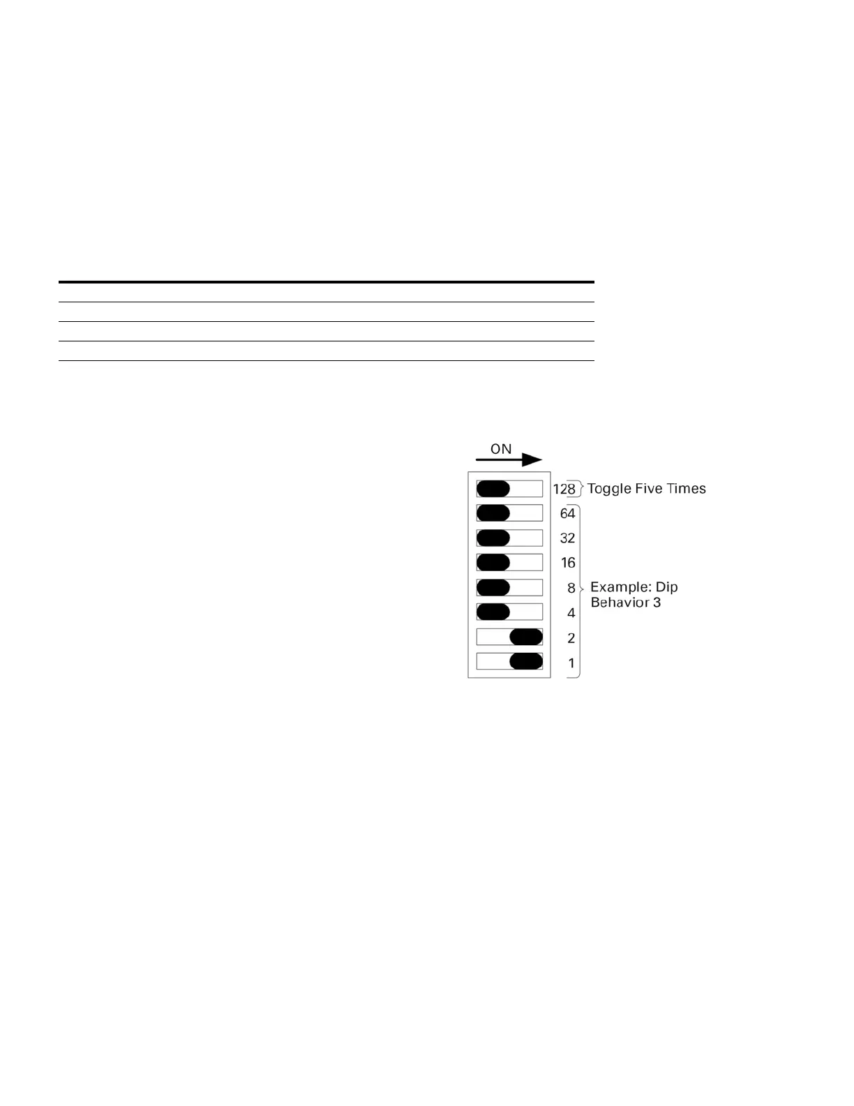
2. Set the DIP switches on the C441 PROFIBUS module to
a value of three per Figure 13.
3. Toggle the top switch shown in Figure 13 5times
(off-on-off is one cycle). A reset will occur after the fifth
cycle indicated by all LEDs turning ON, then OFF again.
Turn power off to the module.
4. Connect the C441 PROFIBUS module to the new device
or use it as a stand-alone I/O module. When it is
powered up again, it will begin working with the new
device or as a stand-alone I/O module.
Figure 13. DIP Switch Service 3 Example
ON (GREEN,
the left one)
BF (RED,
the middle one)
SF (RED,
the right one)
Fault
Condition
ON OFF OFF Everything OK
ON ON OFF No communication
ON Blinking OFF Communication, but not in data exchange
ON ON ON Configuration not OK

 Loading...


