5
4 Technical data
Installation and Operating Instructions CGLine+ Web-Controller 40071860236 (E) February 2019 www.eaton.com
4 Technical data
Table 1. Technical data
Power supply (typ.) 230 V AC, 50/60 Hz
Power consumption < 4 Watt standby,
< 21 W full load (RMS)
Connection terminals max. 2.5mm² flexible
Permissible ambient tempera-
ture
0...+35°C
Storage temperature -20°C...+70°C
Protection rating IP 20
Housing type DIN rail 12 TE
Dimensions 214 x 109,8 x 60,1 mm
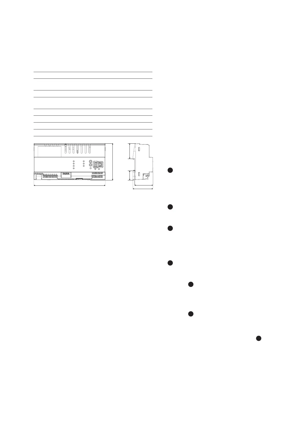
Fig. 2. Dimensional drawing CEAG CGLine+ Web-Controller
4.1 Description / application area
For the central visualisation and control of CGLine+ self-con-
tained luminaires with CGVision software or via the integrated
web interface with a standard web browser (e.g. Internet
Explorer):
n
Complete control and monitoring of up to 800 CGLine+
self-contained luminaires on CGVision (optionally available).
In CGLine mode max. 400 CGLine luminaires.
n
Integrated web server for simple visualisation via standard
web browser
n
Internal logbook on SD memory card
n
Two zero-potential signal contacts, freely programmable
n
Blocking input with differential loop supervision
n
E-mail program integrated in Web server
n
Two option inputs, freely programmable
214
109,8
46,0
28,0
60,1
54,4
5 Installation
Please comply with safety regulations and device safety leg-
islation, as well as valid technical regulations when setting up
and operating electrical operating equipment.
5.1 Assembly
Observe impermissible temperatures at the installation loca-
tion during mounting. The permissible ambient temperature
must not exceed +35°C. The interface is mounted on a DIN rail
(12 TE).
5.2 Electrical connections, push buttons and
LED displays
5.2.1 LED displays
9 coloured LED displays are located on the front plate and 2
LED displays on the ethernet connection with the following
functions:
n
1
Line 1 to Line 4:
n Signalling of sending or receiving data between the
CGLine+ Web-Controller and the CGLine+ self-contained
luminaires. A green LED signals the receipt of data at the
Web-Controller, and a yellow, flashing LED the sending
of data to the luminaires.
n
2
Power LED:
n Lights up green when the controller is connected to the
supply voltage 230V/AC.
n
2
Test LED:
n Flashes green rapidly when the function test for at least
1 luminaire runs
n Flashes green slowly when a duration test for at least 1
luminaire runs
n
2
Failure LED:
n Lights up red when at least 1 random fault is pending,
e.g. luminaire battery defective
n
LED USB1:
4
n Flash yellow during data transmission between the Web-
Controller and a USB device.
n Off when no data transmission in progress.
n
LED USB2:
5
n Flash yellow and green during data transmission.
n Solid green when connected but no traffic in progress.
n
LED display on the LAN (ethernet connection):
9
n Green = flashes with traffic
n Yellow = link or network connection