Connections of wires shall be made with due care to prevent any faults or dead
shorts. Places of connections shall be protected against weather conditions.
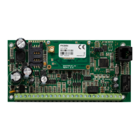
According to the above figure terminals of transmitter shall be connected to:
Terminal
Connection description
AC, AC Two terminals for AC power supply (output from AC
transformer)
GND Device ground, common for other input and output
+ACU Positive terminal of battery
IN1 till IN8 Signal inputs. Possible connection of detectors contacts
or alarm control panel outputs. GND terminal is
common for all inputs
TMP Connection of monitoring sabotage switch (the second
switch contact connected to GND terminal)
NC, NO, C Additional output indication relay. It may control
external device. During activation disconnects C
terminal from NC, and connects C to NO terminal
OUT1 Type OC sabotage output. It may control external
device. Provides ground during activation
+12V Supply voltage output. Provides up to 200mA
RING, TIP Terminals for an PSTN telephone
R1, T1 Connection to alarm control panel phone communicator
NOTES :
OUT1 output can sink up to 100mA. Don’t short this output to power supply
because it can cause permanent damage of output.
Don’t connect power supply when GSM antenna isn’t connected, because it
can cause permanent damage of GSM/GPRS modem.
After careful connections examination a battery may be connected (to +AKU and
GND terminals) and then power may be switched on for transformer and
programming procedure of transmitter may begin (See chapter 6).