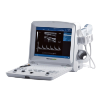
DUS 60 Digital Ultrasonic Diagnostic Imaging System Service Manual
- 42 -
Figure 3-5 Probe Scan Direction Mark Schematic Diagram
There is information about Model and SN on the probe.
To connect a transducer:
1. Place the transducer’s carrying case on a stable surface and open the case.
2. Carefully remove the transducer and unwrap the probe cable.
3. DO NOT allow the transducer head to hang free. Impact to the transducer head could result in
irreparable damage.
4. Turn the connector locking handle counterclockwise to the horizontal position.
5. Align the connector with the transducer port and carefully push into place.
6. Turn the locking handle on the transducer connector clockwise to the vertical position. This
ensures the connector in position and ensures the best possible contact.
7. Place the transducer in the transducer holder.
Figure 3-6 Lock and Open Marks on Probe Connectors
3.9. Configuration
3.9.1. Available Probes
See Chapter 7.3.5 Probes, for part numbers to be used when ordering new or replacement service
probes.
Scan Direction Mark

 Loading...