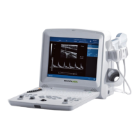
DUS 60 Digital Ultrasonic Diagnostic Imaging System Service Manual
- 90 -
6.7.4. Monitor Troubleshooting
Fault symptom Check these items
Check the power cord is properly connected.
Check the power switch on left of system is set to the “ON”
position.
Check the monitor board power.
The screen is dark
Check the monitor.
Check the video cable on the J6 socket of mainboard is
properly connected.
Check no pins of the video cable are bent.
The screen is gray
Check the mainboard.
Check the probe connection and the probe model.
Check the probe socket board.
No sector image, the whole sector
image is white
Check the mainboard.
There are three
dark channels in
the B image area
Check the 32 pin (from A17 to A32 and from C17 to C32) on
the J1 socket of the mother board. If any of the pin does not
have signal, the mainboard is broken down; if all of them
have signals, the probe or the probe socket may be broken
down.
There is dark
channel when unit
is switched on
Not there dark
channels
Check probe (transducer) is not broken down.
Check probe socket board is not broken down.
Check there is no interference.
Check the probe is not broken.
Image is not clear in far field
Check parameters in the field are adjusted well.
Image in near field is too dark Check there is no air bubble on the lens of probe.
Fuse burn out as the device is
switched on
Check short circuit on the power board.
Probe does not work Check the socket to connect the probe loosens.
No effect when adjusting gain Check the IC is not broken.
Picture is fuzzy Adjust the contrast and brightness.
Video test patterns are not clear, bright,
parallel or square
Replace the monitor.
Table 6-3 Monitor Troubleshooting
The causes of troubles are simply analyzed only for reference; the troubles are not absolutely caused
by above analyzed reasons.

 Loading...