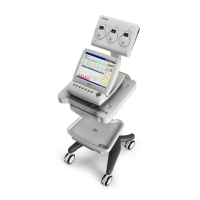
DUS 60 Digital Ultrasonic Diagnostic Imaging System Service Manual
- 44 -
Chapter 4 Components and Functions (Theory)
4.1. Description of the DUS 60 Operating Modes
B Mode
B mode is a two-dimensional image of the amplitude of the echo signal. It is used for location
and measurement of anatomical structure and for spatial orientation during operation in other
modes. Ultrasound echoes of different intensities are mapped to different gray scales on the
screen.
M Mode
In M-mode, soft tissue structure is presented as scrolling display, with depth on the Y-axis and
time on the X-axis. It is used primarily for cardiac measurements such as value timing on septal
wall thickness when accurate timing information is required. M-mode is also known as T-M
mode or time-motion mode. M-mode displays time notion information of the ultrasound data
derived from a stationary beam. Depth is arranged along the vertical axis with time along the
horizontal axis. M-mode is normally used in conjunction with a 2D image for spatial reference.
The 2D image has a graphical line (M-line) superimposed on the 2D image indicating where the
M-mode beam is located.
PW Mode
A pulsed-wave Doppler (PW) scan produces a series of pulsed used to study the motion of blood
flow in a small region along a desired scan line, called the sample volume.
The X-axis of the graph represents time, and the Y-axis represents Doppler frequency shift. The
shift in frequency between successive ultrasound pulses, caused mainly by moving red blood
cells, can be converted into velocity and flow if an appropriate angle between the insonating
beam and blood flow is known.
Shades of gray in the spectral display represent the strength of the signal. The thickness of the
spectral signal is indicative of laminar or turbulent flow (laminar flow typically shows a narrow
band of blood flow information).
4.2. Principle Block Diagram
The DUS 60 is composed of probe, front end, ultrasound echo signal processing, video overlay,
CPU system control, power, peripheral equipment, etc., which is shown in figure 4-1.
 Loading...