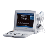
DUS 60 Digital Ultrasonic Diagnostic Imaging System Service Manual
- 51 -
Interface connected to the VGA –J7
Interface connected to the power board –J8
Interface connected to the inverter (to control the LCD backlight) –J9
Pin No. Symbol Pin No. Symbol
1 VGA_OUT_RED 2 VGA_OUT_GREEN
3 VGA_OUT_BLUE 4 reserved
5 GND 6 GND
7 GND 8 GND
9 reserved 10 GND
11 reserved 12 reserved
13 HSYN 14 VSYN
15 reserved / /
Pin No. Symbol Pin No. Symbol
1 D3.3V 2 A12VIN
3 GND 4 D12V
5 D5V2IN 6 A3V7IN
7 GND 8 A-40VIN
9 GND 10 A125VIN
11 D3.3V 12 D3.3V
13 GND 14 GND
15 GND 16 D5V2IN
17 GND 18 GND
19 GND 20 VTXIN
Pin No. Symbol
1 D12V
2 D12V
3 BLGHT_EN
4 LCD_BRIGHTNESS
5 GND
6 GND

 Loading...