210E / 210ECL / 2010 / 2010ECL / 2018ECL SERIES SIGNAL MONITOR
OPERATIONS MANUAL
Eberle Design Inc. Page 11
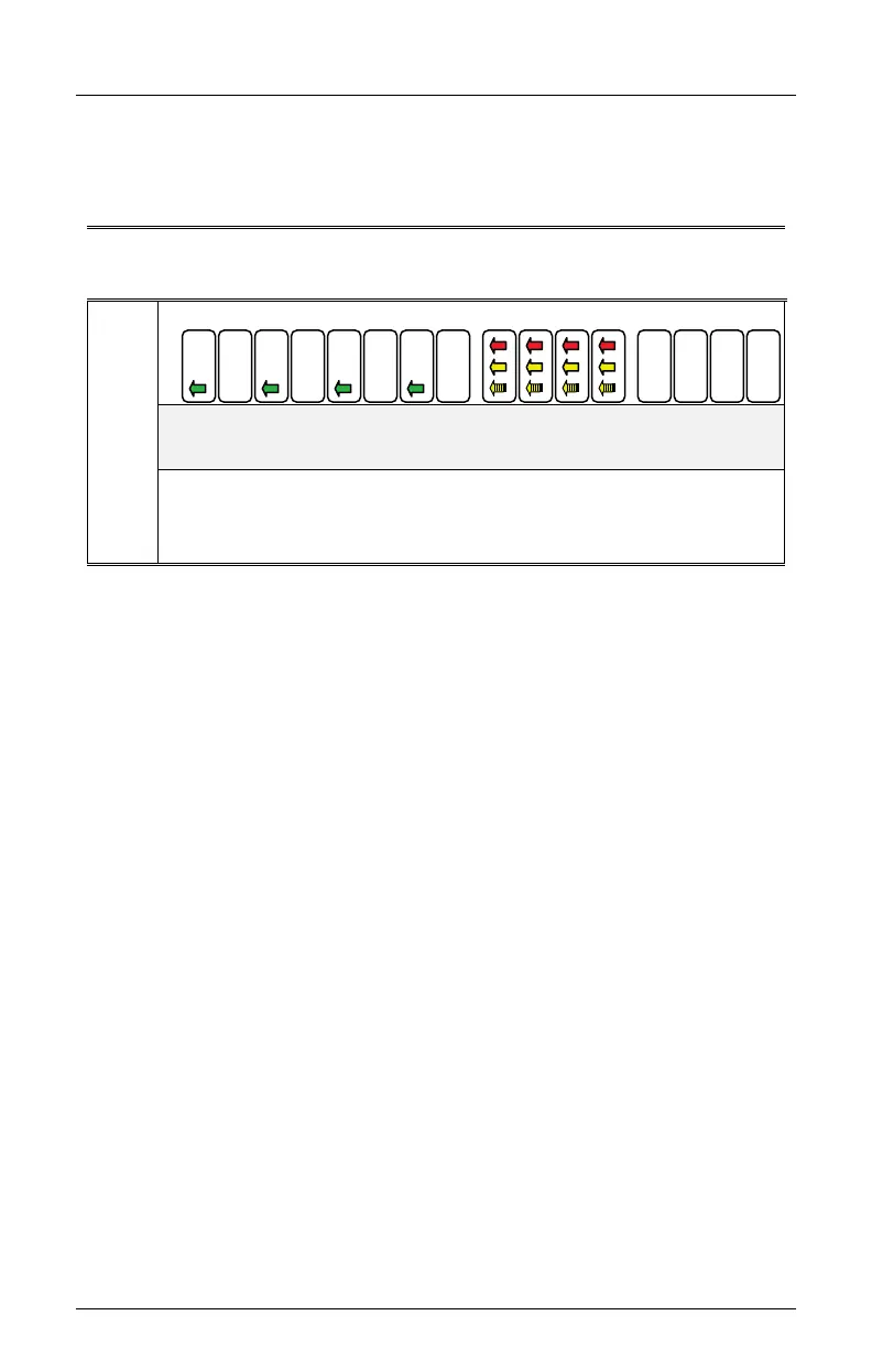
Yellow Arrow (Overlap phase) must be driven by a load switch monitored on channels 9,
10, 11, and 12 respectively. The Signal Monitor associates channel 1 with 9, channel 3 with
10, channel 5 with 11, and channel 7 with 12, when FYA monitoring is enabled for that
respective approach. See Section 4.4.8 for FYA Mode programming.
Table 2-1
FYA Mode Channel Configurations
FYA
Mode
Ch: 1 3 5 7 9 12 13 16
Channels
Through
Channels
Driver Source
2.20.1.1 FYA MONITORING FUNCTIONS
If a FYA channel pair is enabled for FYA operation, the Signal Monitor will monitor the FYA
logical channel pair for the following fault conditions:
2.20.1.1.1 CONFLICT
Channel conflicts are detected based on the Permissive programming jumpers on the
Program Card for each channel. This operation remains unchanged from normal operation
except for the solid Yellow arrow (FYA clearance) signal.
2.20.1.1.1.1 PROTECTED YELLOW CHANGE INTERVAL CONFLICT
The Signal Monitor will verify during the Yellow change interval of the Protected Turn
channel (Green arrow; channels 1,3,5,7) that no conflicting channels to the solid Yellow
arrow channel (clearance) are active. The conflicting channels are determined by the
Program Card compatibility programming of the Protected Turn channel (Green arrow;
channels 1,3,5,7) of the pair.
2.20.1.1.1.2 PERMISSIVE YELLOW CHANGE INTERVAL CONFLICT
During all other times the Signal Monitor will verify that no conflicting channels to the solid
Yellow arrow channel (clearance) are active as determined by the Program Card
compatibility programming of the Permissive Turn channel (flashing Yellow arrow;
Channels 9, 10,11, 12).
2.20.1.1.2 FLASH RATE DETECTION
When the FLASHRATE FAULT option is not disabled (see Section 4.5.7), the Signal
Monitor will monitor a flashing yellow arrow output for a lack of flashing operation. If any of
the enabled flashing yellow arrow signals on channels 9,10,11,12 remain active for more
than the FYA Flash Rate Fault time (Section 8.2), the Signal Monitor will enter the fault
mode, transfer the OUTPUT relay contacts to the Fault position, and display status. The
Signal Monitor will remain in the fault mode until the unit is reset by the RESET button or
the EXTERNAL RESET input.