210E / 210ECL / 2010 / 2010ECL / 2018ECL SERIES SIGNAL MONITOR
OPERATIONS MANUAL
Eberle Design Inc. Page 37
=== Mating connector shall be keyed between pins 24 and 25 and also BB and
CC. The Monitor circuit and the Program Card mate with a 28/56 pin
double sided edge-card connector having 0.156" centers.
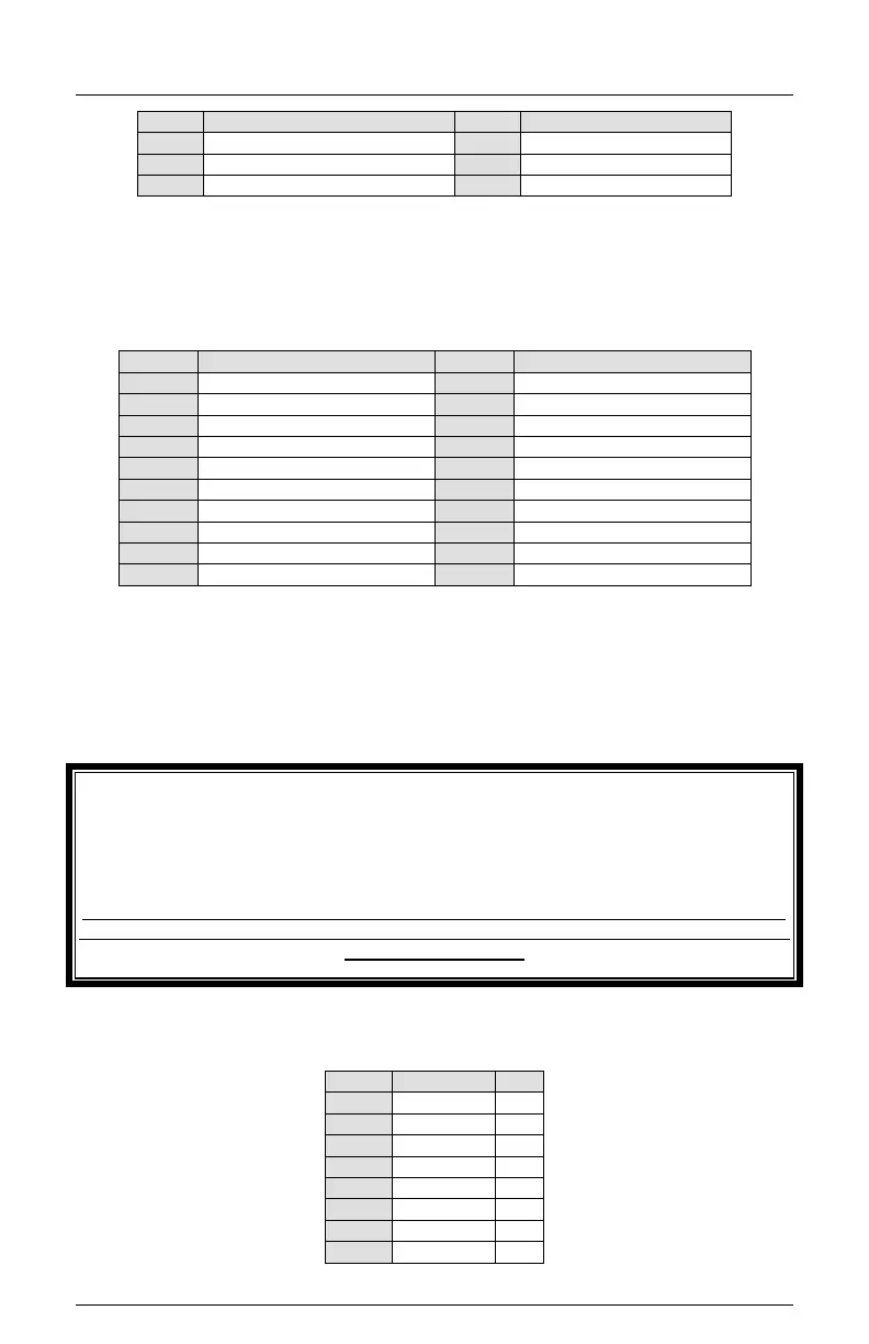
9.3 RED INTERFACE CONNECTOR (P1)
**Note: Pin #4 may be used to connect the monitor chassis to the cabinet CHASSIS
GROUND. To complete this connection, a soldered wire jumper must be placed in location
E1. Monitor CHASSIS GROUND is also connected through the edge connector P6. The
additional connection through the Red Interface cable can provide the CHASSIS GROUND
connection to the monitor if the unit is removed from the cabinet with the Red Interface
cable attached. The cabinet assembly must also be wired to connect the other end of the
Red Interface cable to CHASSIS GROUND.
9.4 EIA-232 CONNECTOR (J1)
- WARNING -
IF JUMPER E1 IS USED BE SURE THAT ANY CABINET WIRING OR MONITOR TEST
EQUIPMENT DOES NOT DRIVE PIN #4 WITH AN ACTIVE SIGNAL. USE OF THIS
CHASSIS GROUND CONNECTION MAY MAKE THE UNIT INCOMPATIBLE WITH SOME
SIGNAL MONITOR TESTERS.
THE P1 RED INTERFACE CONNECTOR SHOULD ALWAYS BE UNPLUGGED BEFORE
REMOVING THE UNIT FROM THE CABINET TO PREVENT POTENTIAL EXPOSURE TO
ELECTRICAL SHOCK.