210E / 210ECL / 2010 / 2010ECL / 2018ECL SERIES SIGNAL MONITOR
OPERATIONS MANUAL
Eberle Design Inc. Page 13
To enable channel pair for FYA operation, place the Option DIP Switch labeled “FYA x-y”
(where “x-y” is 1-9, 3-10, 5-11, or 7-12) in the On position. When the “FYA x-y” switch is in
the Off position, both channel x and y operate in standard fashion. See Section 4.4.8.1.
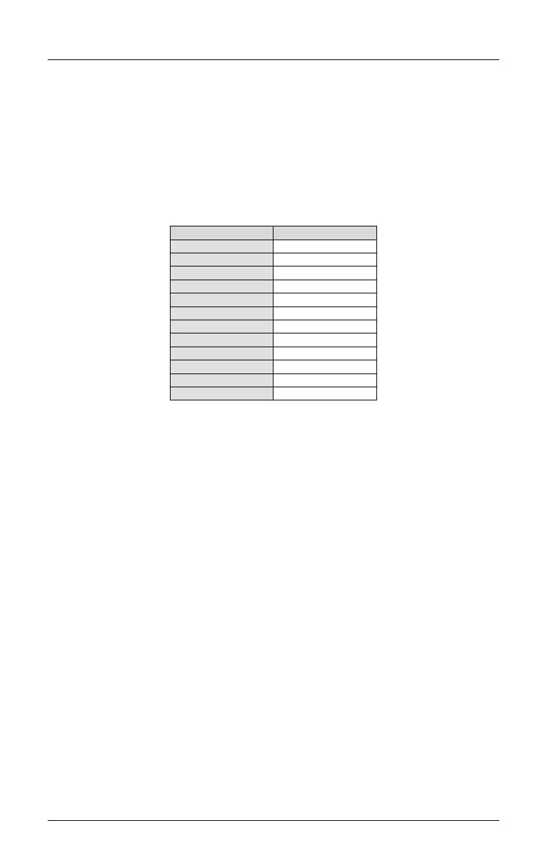
This Permissive Programming (Conflict Matrix) assignment example assumes standard
channel assignments for an eight phase quad intersection. The Permissive programming
for channels 1, 3, 5, and 7 (solid Green Arrow) are unchanged from conventional
programming for a protected left turn phase, with the addition of the jumpers for the
associated FYA overlap channels. The Permissive programming for overlap channels 9,
10, 11, and 12 (solid Yellow and flashing Yellow Arrow) must be set with similar
programming to the associated through phase. For example:
Note: This example is for illustrative purposes ONLY. Permissive Programming for
an application depends on actual intersection geometry, cabinet wiring, and
Controller programming.
2.20.1.3 RIGHT TURN OVERLAPS
Because the FYA operation uses channels 9 through 12 normally assigned to overlap
phases, a sixteen channel monitor does not provide enough channels for an eight phase
intersection with four pedestrian channels, four right turn overlaps, and four FYA
approaches. Right turn overlaps can still be implemented by driving the right turn signal
heads with the corresponding protected left turn load switch. In this case, the right turn
overlap will not be controlled independently. Consideration should be given for the SSM
switch being On for the channel 1, 3, 5, and 7 if used in this manner.
For right turn overlaps with no Yellow Arrow, consideration should be given to driving the
Green Arrow load switch input with the Phase On control.
2.20.2 FYAC (COMPACT) MODE
For each FYAc approach (see Table 2-2), each solid Green protected Arrow signal is
monitored on channels 9, 10, 11, and 12 (Green). The associated solid Red Arrow, solid
Yellow Arrow, and flashing Yellow Arrow is monitored on channels 1, 3, 5, and 7
respectively. The Signal Monitor associates channel 1 with 9, channel 3 with 10, channel 5
with 11, and channel 7 with 12, when FYAc monitoring is enabled for that respective
approach. See Section 4.4.8 for FYA Mode programming.
In the FYAc mode the Signal Monitor requires that the protected Green arrow signals be
driven by the unused Ped Yellow load switch outputs. This relies on a Caltrans cabinet
wiring requirement of connecting the Ped Yellow load switch outputs to monitor channels 9
and 10 as described in section 2.20.2.2. Using this scheme allows a standard twelve
position Output File to provide the necessary signals without the addition of an Auxiliary
File.