210E / 210ECL / 2010 / 2010ECL / 2018ECL SERIES SIGNAL MONITOR
OPERATIONS MANUAL
Eberle Design Inc. Page 15
The SSM Switch for each channel must be in the ON position to enable Red Fail Monitoring
for that channel.
2.20.2.1.4 DUAL INDICATION
A Dual Indication fault will occur if any two or more of the solid Red Arrow, solid Yellow
Arrow, flashing Yellow Arrow, or solid Green Arrow signal combinations are active
simultaneously for the Dual Indication fault response time. The fault channel status will be
indicated for the FYAc channel (1, 3, 5, 7). The fault channel status will also be indicated
for the solid Green Arrow channel (9, 10, 11, 12) IF the solid Green Arrow was active.
2.20.2.1.5 CLEARANCE
A Clearance fault will be detected if the FYAc channel sequences from the solid Green
Arrow (9, 10, 11, 12) to the solid Red Arrow (1, 3, 5, 7) without a minimum clearance time
on the solid Yellow Arrow (1, 3, 5, 7), when SSM switch 1, 3, 5, 7 is On. The fault channel
status will be indicated for the FYAc channel (1, 3, 5, 7).
A Clearance fault will be detected if the FYAc channel sequences from the flashing Yellow
Arrow (1, 3, 5, 7) to the solid Red Arrow (1, 3, 5, 7) without a minimum clearance time on
the solid Yellow Arrow (1, 3, 5, 7), when SSM switch 1, 3, 5, 7 is On. The fault channel
status will be indicated for the FYAc channel (1, 3, 5, 7).
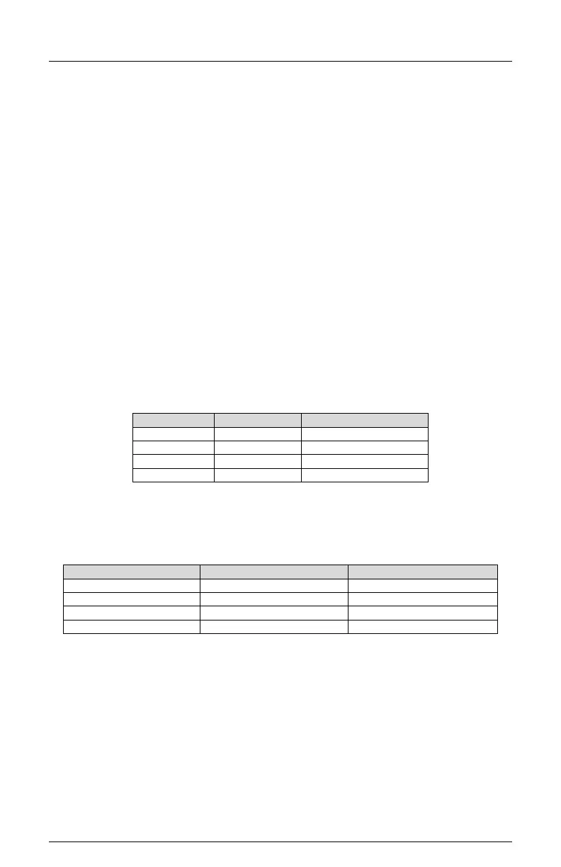
2.20.2.2 FYAC INSTALLATION
The cabinet must be wired such that the (unused) Ped Yellow load switch outputs are wired
to the Signal Monitor inputs as follows:
The Controller unit must be configured to drive the protected Green arrow signals from the
Ped Yellow load switch outputs. If ANY channel pairs are enabled for FYAc operation, the
Signal Monitor will internally remap monitor Channel 9 and 10 physical inputs such that the
protected Green arrow signals will be monitored as Channels 9, 10, 11, and 12 as follows:
The associated solid Red Arrow, solid Yellow Arrow, and flashing Yellow Arrow phases
must be driven by a load switch monitored on channels 1, 3, 5, and 7 respectively. The
Signal Monitor associates channel 1 with 9, channel 3 with 10, channel 5 with 11, and
channel 7 with 12 when FYA monitoring is enabled for that respective approach.