Without fail, the PE conductor must be connected in the fixed con-
nection and the loop resistance be maintained until the last load. It
is also possible to separately secure and to directly ground the
loads against excess and residual current.
Always pay attention to the correct polarity between the in- and output of the
UPS. If the UPS is located in an emergency stop circuit, it must be noted that,
after the activation of the emergency stop circuit, the UPS output is not without
current. The loads will continue to be supplied during the duration of the UPS
autonomous period.
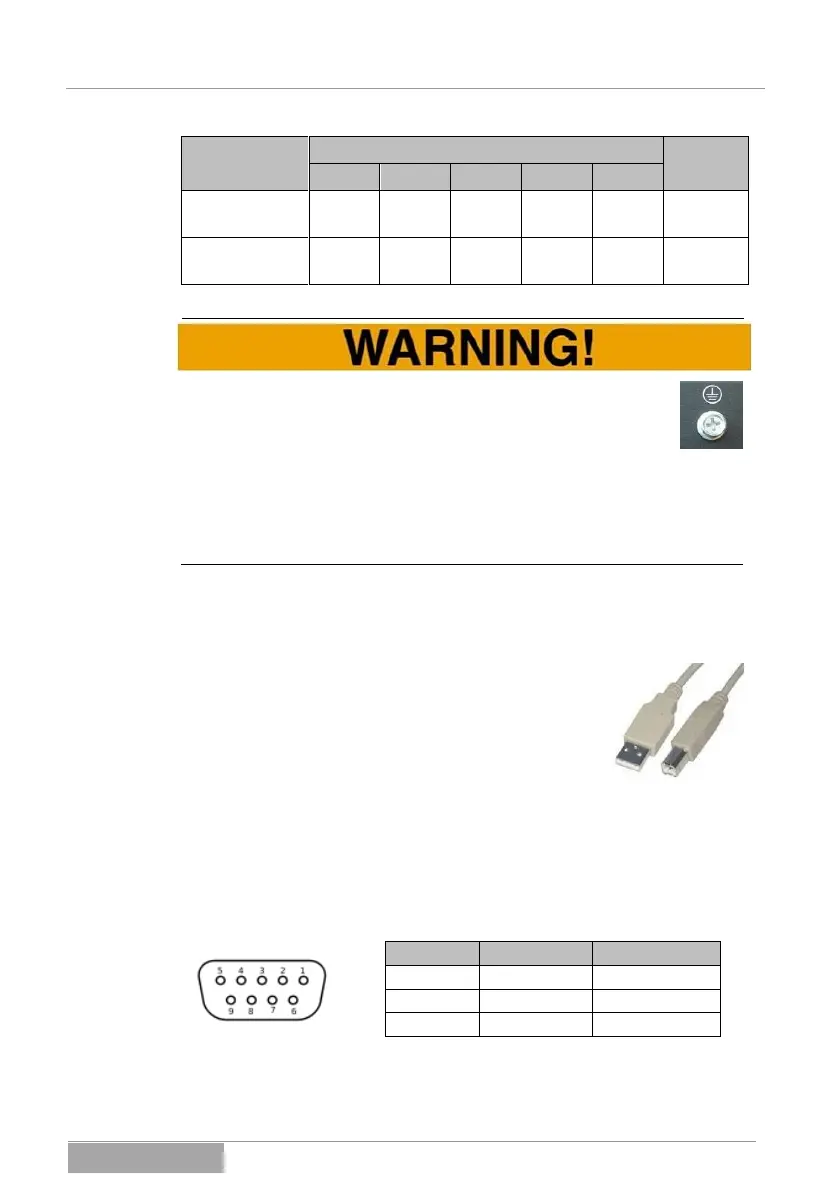
5.1.2 Connection of the communication port USB
Please use the USB cable (type A to type B) for connect-
ing the USB communication port and use it to connect the
UPS to your PC or hub. The USB port is a “PLUG &
PLAY” connection (HID-DEVICE). Further actions are not
necessary. Additional information can be found under
Chapter 11 Monitor software.
5.1.3 Connection of the communication port RS232
The serial port RS232 serves to couple the system with a PC or the application
installed on it (software).
The connection is likewise designed for a serial standard cable and the alloca-
tion is described below (pins not listed are unallocated):
 Loading...