3.3 Device components of the UPS
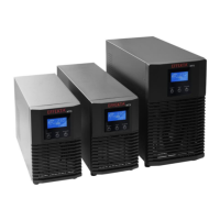
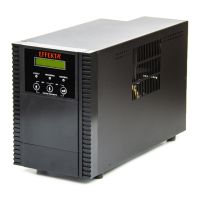
The complete MTX device series is integrated in a free-standing enclosure
(TOWER). All device elements for the operation and display are accessible on
the front of the device. The elements for the connection and extensions of the
device are arranged on the back side. All communication connections are also
located on the back of the device.
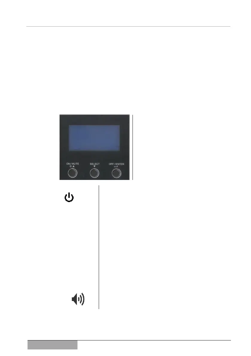
3.3.1 The operating panel of the UPS
In this device series, the control panel is reduced to three buttons and the de-
vice display:
All information is shown on the device dis-
play during operation. A summary of the
device messages is found in chapter 8
Messages and error codes.
There are 3 buttons for the operation of the
device. Each of these are assigned several
functions. An overview of this follows, an
exact description is found under 6 Opera-
tion of device and service.
This button switches the device on (ON), mutes acoustic
alarms (MUTE) or starts the self-test mode of the device.
Also, touching the button can scroll backwards within the
setting menu or perform upwards counting.
This button selects an information display (INPUT, OUTPUT,
BATTERY etc.). It also takes you to the setting mode. Fur-
thermore, touching the button can scroll forwards within the
setting menu or perform downwards counting.
The UPS can be switched off with this button. In addition,
this button serves as the confirm button or the enter button
in the setting mode.
By simultaneously pressing on both these buttons (ON,
SELECT) during the setting mode, you will go to the previ-
ous menu. If you are already at the first menu item, you can
exit the setting mode with the button combination.
In addition to the information displayed, several operation,
warning and alarm messages are supported acoustically by
the built-in signal generator (BUZZER).
3.3.2 UPS Display
The status and additional information about the system can be called up on the
LC display or critical parameters can be set. Primarily, the current status infor-