mation or operating information and the available alarm codes in the case of
failure are important. The total display contains various information areas and
pictograms.
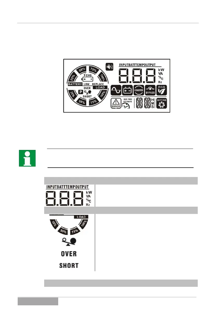
Fig. 3-3 Example of view of total display.
In the following, the meaning of the information shown is explained in detail. Ad-
ditional and supplementary information for the display and notices can be seen
under 8 Messages and error codes:
Due to progressive improvements in the software, additional information can al-
ready exist that has not yet been addressed in detail here. It is thus possible
that some page content has been changed accordingly.
Operation data of the UPS:
Value display: here the input data (voltage, frequen-
cy), the output data (voltage, frequency, charging
current or load in %) and the device temperature are
displayed.
Load information for the UPS:
The lower circle bar display also shows the load in
%. The gradations are: 2-24%, 25-49%, 50-74%, 75-
100%.
This symbol indicates that the UPS output is
switched on.
This symbol indicates that the UPS output is over-
loaded.
This symbol indicates that the UPS output has a
short circuit.
Battery bank information of the UPS:
 Loading...