ELECTRIC AND PNEUMATIC DIAGRAMS
NP-eVENT-16_10-2018 23
EV1 EV2
YV1
1 2 3
40°C
ST1
4 5 6 7 8 9 10 11 12 13 14
HL2
80°C
ST2
HL1
RD
GN
1
gnye
bk
gy
bn
M1
M
Motor Soft Start-Stop
PCB
PE
U N
PH
0000
h
C
B1
1/N/PE ~ 115/230 V 50/60 Hz
ELECTRIC OBJECT OF 1st CAT.
XC
EV1 EV2
YV1
1 2 3
40°C
ST1
4 5 6 7 8 9 10 11 12 13 14
HL2
80°C
ST2
HL1
RD
GN
Motor Soft Start-Stop
PCB
PE
U N
PH
0000
h
1/N/PE ~ 115/230 V 50/60 Hz
ELECTRIC OBJECT OF 1st CAT.
XC
M1
1
M
B1
C
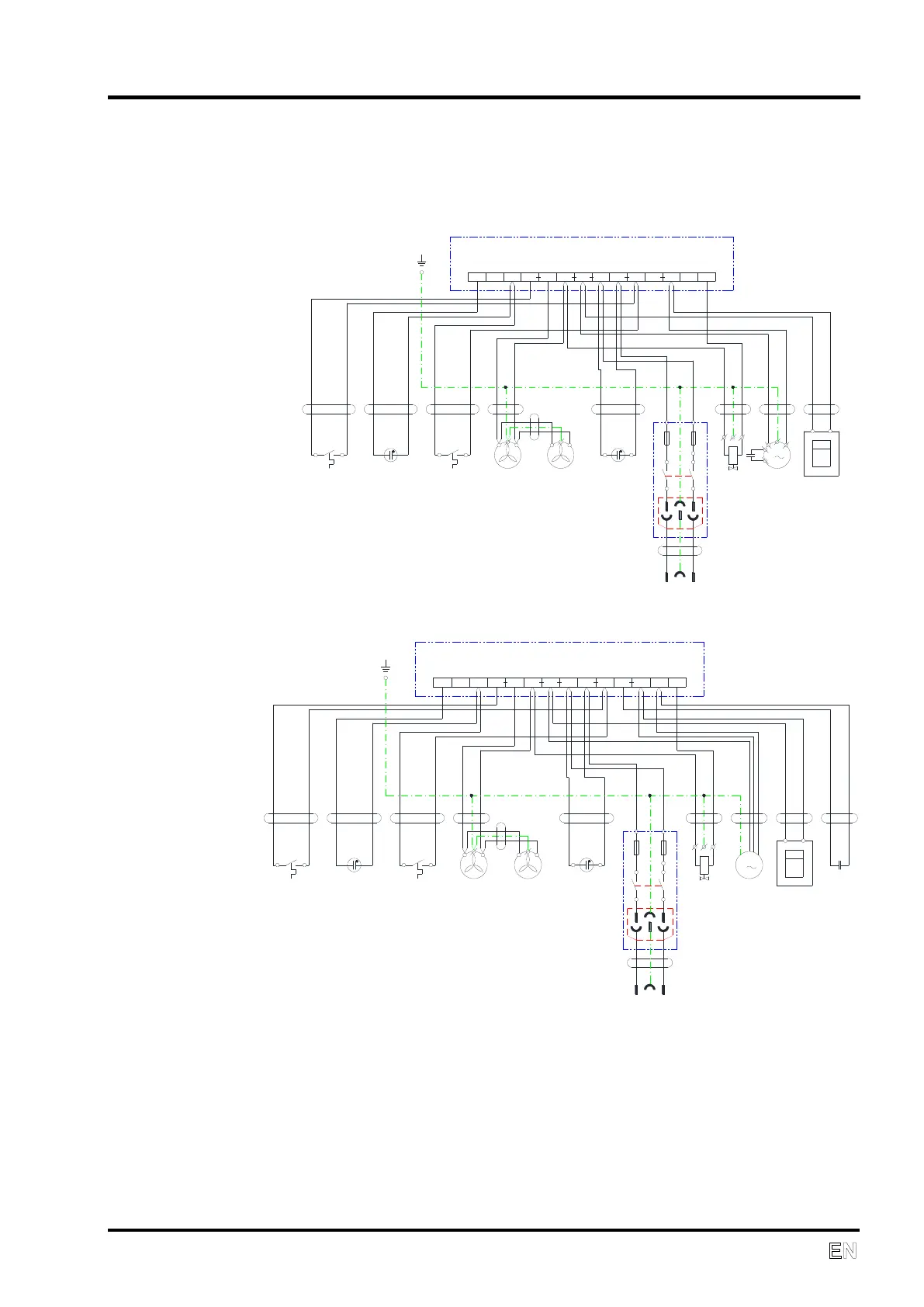
8. ELECTRIC AND PNEUMATIC DIAGRAMS
WIRING DIAGRAM
DK50 D
DK50 DM
Note
Wire entering the terminal should be marked with marking element with corresponding
number.
Des. Name Des. Name
HL1,HL2 Glow lamp M Electric motor
EV1,EV2 Ventilator ST1,ST2 Thermal switch
PH Hour meter XC Socket with fuses
YV Solenoid valve Cb1 Capacitor