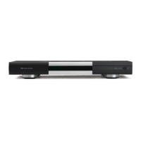
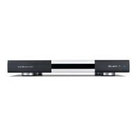
ELAN HC6/HC12 INSTALLATION MANUAL
© ELAN 2010 | All rights reserved.
Page 50
Chapter 6: Troubleshooting
General
Serial Devices
Symptom Possible Cause Solution
HC6/HC12 will not
power up.
1. Power cable disconnected
2. Power switch is off
3. Circuit breaker tripped
1. Connect power cable
2. Turn power on
3. Reset circuit breaker
Symptom Possible Cause Solution
No control of serial
device.
1. Faulty wiring / incorrect DB9 to
RJ 45 adapter
1. Correct wiring / use correct DB-9 to RJ-45 adapter
(See the Integration Notes for the device.)
2. Device connected to incorrect port 2. Connect to correct port – verify port in the configuration
software.
3. Incorrect driver loaded in the
configuration software
3. Select correct driver in the configuration software
5. Serial port settings incorrect on
device
5. Correct port settings (baud rate, stop bits, etc.) of the
device (See the Integration Notes)
Serial port settings incorrect in
dealer created one-way driver
Correct port settings (baud rate, stop bits, etc.) of the
driver, see device manual for correct settings
7. Serial cable too long 7. Verify cable length, move equipment, use RS-232 to RS-
485 adapters
8. Device requires full hand-shaking 8. Device must be on Comm port 1 or Comm port 2.
Control of device
but no feedback
1. Faulty wiring on RECEIVE pins
2. Serial cable too long
3. Incorrect driver
1. Correct wiring – verify RECEIVE using Comm port LEDs
(See Page 36 for LED function)
2. Verify cable length, move equipment, use RS-232 to RS-
485 adapters
3. Correct driver
Feedback from
device but no
control
1. Faulty wiring on TRANSMIT pins
2. Serial control not enabled on device
3. Serial cable too long
4. Incorrect / No Password (on
Security Systems)
1. Correct wiring – verify transmitting using Comm port
LEDs. (See Page 36 for LED function)
2. Enable serial control.
3. Verify cable length, move equipment, use RS-232 to RS-
485 adapters
4. Use correct password
Verify Serial activity using the Serial port LEDS. See page 36 for information.