5
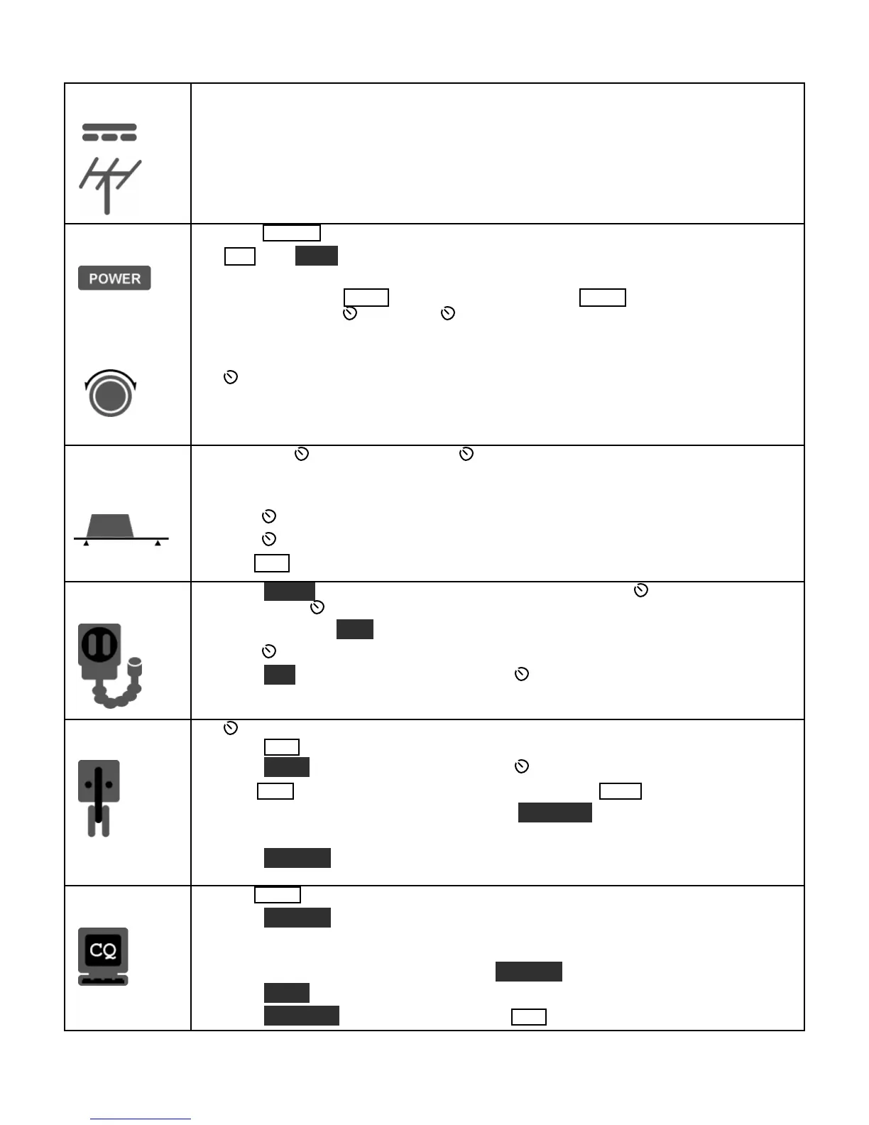
Connections
Connect a power supplyto the DC input jack {26}(see Specifications, pg. 8).
On the K3/100, a circuit breaker is provided on the fan panel for the 100-W stage {30}
You can power an accessory device from the switched DC output jack {38}(0.5 A max).
Connect an antenna to ANT1 {29}. If you have an ATU installed (pg. 22), you can connect
a second antenna to ANT2 {28}. Ifthe KXV3 is installed, you can connect a separate RX
antenna to RX ANT IN {34}. The AUX RF connector {27} is optional; see pg. 17.
The Basics
Press POWER {5}to turn on the K3. If there are any error indications, refer to pg. 63.
TAP and H OLD Functions: Tapping briefly activates the function labeled on
Holding for about 1/2 second activatesthe function labeled below a switch.
Tap either end of BAN D {7}to select a band, andtap MOD E {6}to select the mode. Set
the AF gain using AF {2}. Set RF to max. SUB controls are discussed on pg. 37.
The large knob {22} controls VFO A (upper display, {10}). The medium knob {19}
controls VFO B (lower display, {11}). VFO A is main RX/TX except in SPLIT (pg. 36).
CM P / PWR is one of four multifunction controls {24}. Each hastwo primary
functions, indicated by green LEDs. The knob has a built-in switch; tap it to select either
CM P (compression level) or PWR (power output). Holdthe knob in to access its
secondary function, M ONitor level. Tap again to restore the primary function.
Filter
Controls
Rotate the SHIFT / LOCUT and HICUT / WIDTH controls {23}to adjust the filter
passband. Crystal filters FL1-FL5 are automatically selected as you change the
bandwidth. Tap either knobto alternate between shift/width and hicut/locut.
Hold SHIFT / LOCUT to NORM
alize the bandwidth (e.g., 400 Hz CW, 2.8 kHz SSB).
Hold HICUT / WIDTH to alternate between two filter setups, I and II (per-mode).
Tap XFIL {13} to select crystal filters manually; this also removes any passband shift.
Voice Modes
{1}
Hold METER {8}to see CMP / ALC levels. Whiletalking, set MIC {25} for 4-7 bars
of ALC, and CMP for the desired compression. Then return to SWR / PWR (pg. 28).
Optional: Hold TEST {6} for TX TESTmode; allows off-air TX adjustments (pg. 13).
Hold CMP / PWR {24}to set speech MONitor level; tap to returnto CMP / PWR.
Hold VOX {7}to select PTT or VOX. Hold SPEED / MIC to set VOX DELAY.
Details: VOX, pg. 29; TX EQ, pg. 35; MIC SEL, pg. 51; SSB/AM/FM, pg. 28.
CWMode
{36}
SPEED {25} setsthe CW keyer speed. Holdthisknobto set semi-break-in DELAY
Hold QSK {7}to select full break-in (QSK icon on) or semi-break-in. (Pg. 30.)
Hold PI TCH {18}to set sidetone pitch. Hold CMP / PWR to set sidetone MON level.
Tap CWT {18} for tuning aid {9} (pg. 34). With CWT on, SPOT auto-tunes (pg. 30).
To select CW text decode/display mode, hold TEXT DEC {18}; rotate VFO B (pg. 30).
CW keying is convertedto DATA in FSK D and PSK D modes (below and pg. 34).
Hold DU AL PB {13}to turn CW dual-passband filter (pg. 30).
Data Modes
{31}
Tap MOD E {6} until you see the DATA icon turn on (see Data Modes, pg. 31).
Hold DAT A MD {18}. Use VFO B to select from: DATA A (PSK31 & other
soundcard-based modes), AFSK A (soundcard-based RTTY), FSK D (RTTY via data
input or keyer), or PSK D (PSK via data input or keyer). VFO A selects data baud rate
for internal encoder/decoder, if applicable. DU AL PB turnson RTTY filter (DTF, pg. 32).
Hold PI TCH {18}to select mark tone and shift (for encoder/decoder and RTTY filter).
Hold TEXT DEC {18} to set up text decode. CWT shows tuning aid (pg. 34).