Turn the K3 right side up. Unplug all filtersto be repositioned (those whose mounting screws have been
removed). Lift the filters at each end carefully, first one endthen the other, until the connectors separate.
Reposition the filters asrequired. They will only fit one way. If you put one in backwards, it will not fit
within its outline, and the standoff will not line up with the screw hole inthe RF board (or sub receiver board).
Turn the K3 (or sub receiver module) upside down again. Install the mountinghardware shown below.
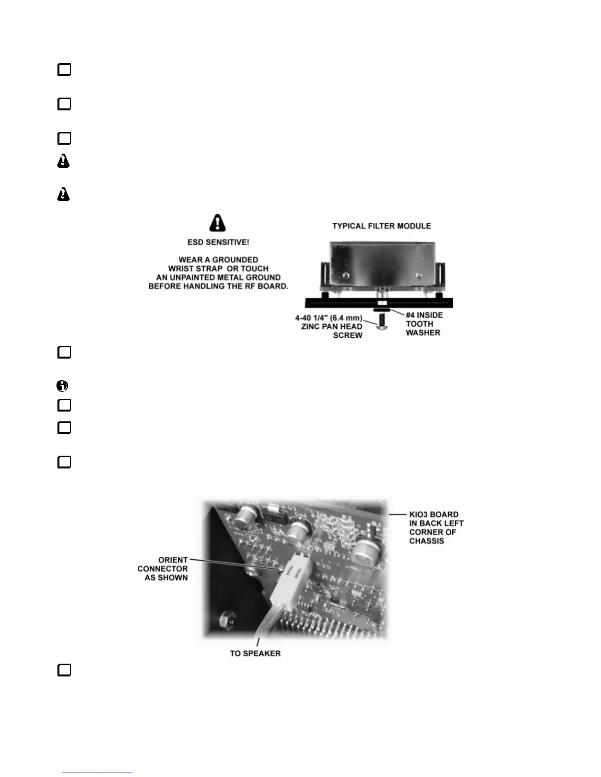
Filters may be supplied with either a black 3/16” or bright-plated 1/4” pan-headscrew. A screw
longer than 1/4” may extend into the 8-pole filterunit and damage it.
Do not over-tighten the screws. Excess torque may pull out the threadedstandoff.
Re-install the bottom cover (if applicable) using seven 4-40 x 3/16” black pan head screws. Replace the
screws securely, but do not over tighten them. All screws must be used to maintain shielding performance.
The top cover and sub receiver (if applicable) will be re-installed in at later step.
Turn to Crystal Filter Setup (pg. 45). Follow all instructions for the main receiver andtransmitter.
If you have the KRX3 option, re-install the sub receiver module as described in the KRX3 manual. Then
turn to Crystal FilterSetup and follow all instructions for the sub receiver.
Position the top cover on the K3, with its rear tab inserted underthetop edge of the rear panel. Then plug
the speaker wire into P25 onthe KIO3 board at the left rear of the K3.
Secure the top cover with 4-40 x 3/16” flat head screws at all locations.
This completes crystal filter installation.