Band Outputs (BAND0-BAND3)
BAND0-BAND3 are open-drain band selection
outputs, with internal pull-up resistors to 5 V. Their
behavior is controlled by CONFIG:KIO3B (see
below). Band data is based on VFO A’s frequency.
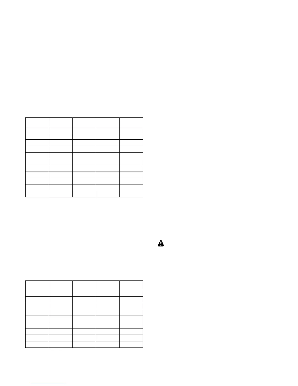
In tables below, 0 = pulled to ground (0 V). 1 =
floating to 5 V. External pull-up resistors can be
connected a voltage not exceeding 14 V.
With CONFIG:KIO3B set to NOR, the BAND0-3
outputs are mapped based on the selected HF-6 m
band as shown below. On transverter bands,
BAND0-3 will all be set to zero.
If CONFIG:KIO3B is set to TRN, BAND0-3
reflect the parameters of the CONFIG:XVn ADR
menu entry, as shown below. On HF-6 m they’re
set to 0. Addresses INT. TRN0-9 are used with
the internal 2-m transverter option (K144XV). INT
TRN0 sets all band outputs to 0, while INT
TRN1-9 have the same decodes as TRN1-9.
Transverter addresses are also sent to Elecraft XV-
series transverters and the KRC2 band decoder
accessory via the AUXBUS line. Note: TRN1-7
are sent as 1-7, but TRN8-TRN9 are sent as 0.
With CONFIG:KIO3B set to HF-TRN, the
BAND0-3 outputs follow the NOR table when HF-
6 m bands are selected, and the TRN table when a
transverter band is selected.
Transverter Control
Normally, when the K3S is turned on, a 5-VDC
logic signal appears on ACC pin 7 (K3S ON). This
could be used with Elecraft XV transverters as an
enable signal (pin 8 of J6 on the transverter).
However, pin 7 can alternatively be configured as a
transmit inhibit input line for use in multi-
transmitter stations. (See TX INH, below.) In this
case it is not available as a power-on signal for
Elecraft transverters. Instead, the transceiver’s 12-
VDC switched output could be used as a transverter
ON signal.
For transverter keying, you can use KEYOUT-LP
signal (pin 10 of the ACC connector) or the KEY
OUT jack (RCA).
With KIO3B set to TRN or HF-TRN, the
DIGOUT0 line (ACC, pin 6) will output 0 V when
low power mode is selected for the current
transverter band (CONFIG:XVn PWR). At all
other times, DIGOUT0 will be floating (Hi-Z).
TX INH (Transmit Inhibit Signal)
Pin 7 of the ACC connector can be configured as a
transmit inhibit input by setting CONFIG:TX INH
to LO=Inh (or HI=Inh). Holding pin 7 low (or
high) will then prevent transmit. An external 2.2 to
10 K pull-up resistor (to 5 VDC) is required.
If TX INH is set to OFF, pin 7 reverts to its
default output function, K3S ON (see above).
Elecraft KRC2 Universal Band Decoder
An Elecraft KRC2 can be used with the K3 to
perform station switching functions; it includes sink
and source relay drivers for all bands. The KRC2
obtains band data via the AUXBUS rather BAND0-
3. (See CONFIG:KRC2 for 6-m band mapping).
Refer to the KRC2 instruction manual for more
information.
 Loading...


