RS232 Adapter Cable
The supplied Elecraft #E970297 cable converts
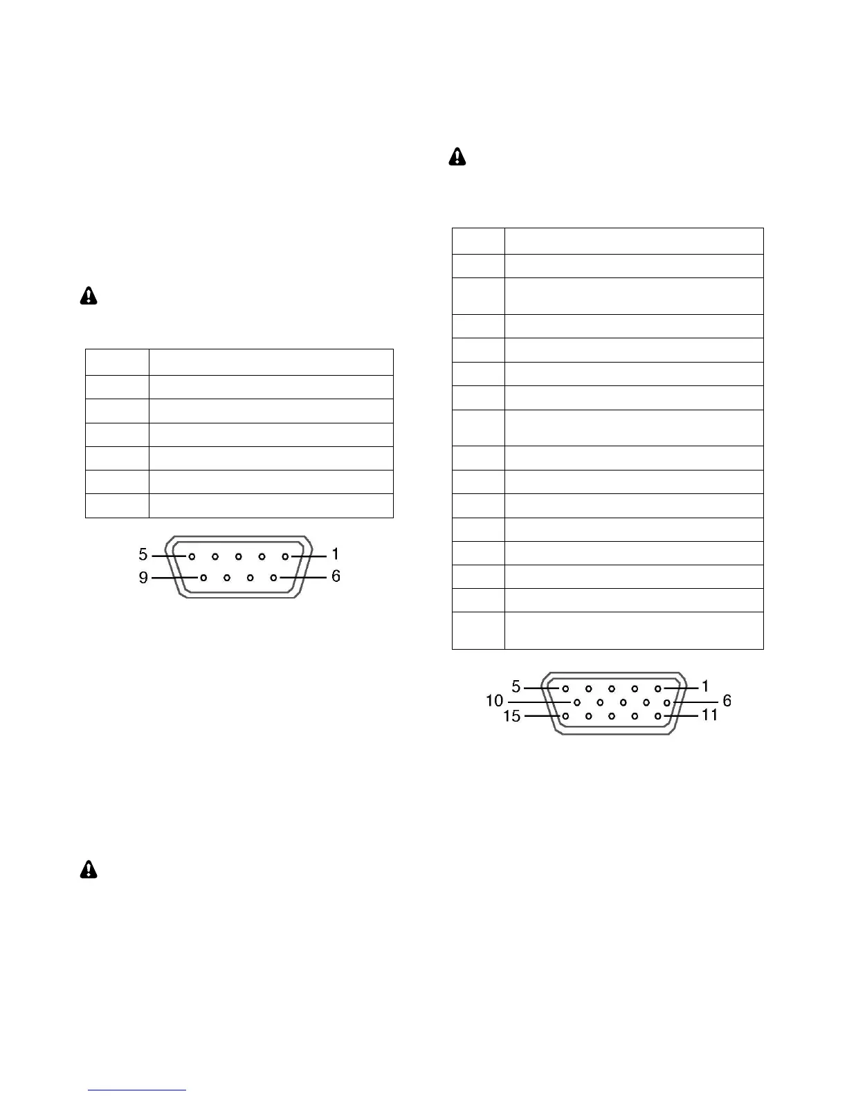
from RJ45 (at the K3S end) to DE9 (RS232
standard). The DE9 end can be connected to a P3’s
XVTR jack, or to a computer’s RS232 port. The
pinout for this end of the adapter is shown below.
If an additional RS232 cable is required to reach
your computer, it can be wired straight-through,
using as few as three wires (RXD, TXD, and
ground). DTR and RTS are optional.
This table uses EIA standard descriptions,
which are from the perspective of the PC.
RXD IN (data to PC from K3S)
TXD OUT (data to K3S from PC)
DTR (see PTT and Keying, below)
RTS (see PTT and Keying, below)
RS232 adapter cable DE9 connections (female)
Serial Port Setup: Set CONFIG:RS232 for the
desired baud rate. Software should be set up at the
same rate; 8 data bits, no parity, 1 stop bit.
PTT and Keying (via DTR and RTS)
In the K3S, these are not used as serial I/O
handshaking lines. Instead, the K3S can use these as
PTT IN or KEY IN (see CONFIG:PTT-KEY). The
default for both signals is inactive. Refer to
application software documentation to determine if
it can use RS232 signal lines for PTT or keying.
Use these signals with caution. A computer
may assert DTR or RTS during power-up, causing
the K3S to transmit unexpectedly. If a computer or
other device asserts RTS or DTR while you’re
using the PTT-KEY menu entry, the K3S will enter
TEST mode as a precaution, allowing you to
change the menu setting if required.
ACC (Accessory I/O)
ACC connector pinouts are listed below.
ACC is not a VGA video connector. The K3S
does not provide a video output. (The P3 does
have an SVGA video output option; see pg. 47.)
AUXBUS IN/OUT (see KRC2 or XV-
Series transverter instruction manual)
BAND1 OUT (see Band Outputs)
PTT IN (in parallel with MIC PTT)
DIGOUT0 (see Transverter Control)
K3S ON signal (out) or TX INH (in)
(see Transverter Control, TX INH)
BAND2 OUT (see Band Outputs)
KEYOUT-LP (10 mA keying output)
BAND0 OUT (see Band Outputs)
BAND3 OUT (see Band Outputs)
EXT ALC input (see External ALC,
pg. 29)
ACC Connector (female, on KIO3B panel)
FSK Input (for FSK D Data Mode)
This is a TTL input pulled up to 5V, compatible
with PC outputs. When used with an RS232 signal
from the PC, a level translator is required.
DIGOUT 1
DIGOUT1 is a per-band/per-antenna output for
controlling external gear. See CONFIG:DIGOUT1.