Instruction Manual
C
HAPTER
2:
Installation
Installation
All wiring and mechanical instructions described in this section should be made with reference
to the “Simplified Circuit Diagram” on page 7-2 and the “Outline, Mounting and Adjustments
Diagram” on page 7-1. Also see “Input Power/Motor Wiring” diagrams starting on page 2-4.
Internal Adjustments
Jumpers
There are jumpers on the velocity regulator board of the MAX-430 to indicate desired operation
of the Forward and Reverse Amplifier Clamps and the System Status Output (FAC, RAC, and
SSO). There are also jumpers used to indicate desired operation of the optically isolated tran-
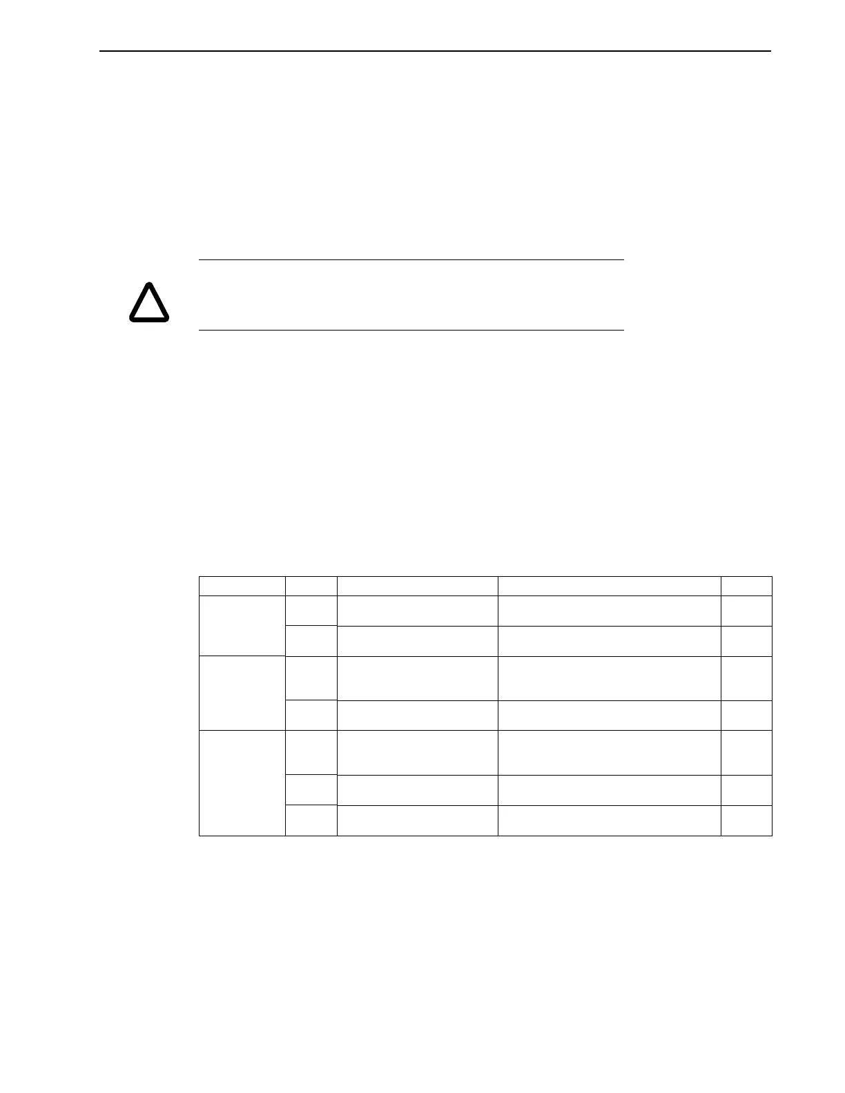
sistors on FAC, RAC and inhibit (INH) inputs. Refer to Table 2.1 for operation of the inputs and
outputs with jumpers P6 through P9A in the different positions. Also see on “Forward and
Reverse Amplifier Clamps (FAC, RAC)” on page 2-10.
Intro
!
CAUTION
If replacing a MAX-400 with a MAX-430, refer to Appendix A, “Differences from
the MAX-400” for a list of changes to be aware of.
T
ABLE
2.1
Inputs and Outputs with Jumpers P6 through P9A
Jumper Pins Position Operation Page
P6 1-2 FAC ILIMIT Current reduced to 5% of peak current in
the forward direction when FAC is clamped.
2-10
2-3
∗
FAC DISABLE No tor
ue in the forward direction when
FAC is clamped.
2-10
P7 1-2 RAC ILIMIT Current reduced to 5% of peak current in
the reverse direction when RAC is
clamped.
2-10
2-3
∗
RAC DISABLE No tor
ue in the reverse direction when
RAC is clamped.
2-10
P8 1-2
∗
Internal Opto Power Opticall
isolated transistors
opto’s
on
FAC, RAC and INH inputs are powered
internall
b
the drive.
2-11
P8A 1-2
∗
Internal Sourcin
Opto’s Opto’s are sourcin
inputs
pulled up to 24V
b
internal power when true
.
2-11
P8A 2-3 Internal Sinkin
Opto’s Opto’s are sinkin
inputs
pulled down to
0V b
internal power when true
.
2-11