4-2 Diagnostics/Troubleshooting
P/N 0013-1025-001 Rev F
Scheduled Maintenance
The MAX-430 Series drives have been designed to require minimum maintenance.
The following are suggestions for preventive maintenance:
1. Keep the drives as clean as possible. This will result in cooler operation and more reli-
able performance.
2. Periodically check that all connections and fasteners are tight.
3. Check the incoming AC line occasionally for high or low voltage condition. If the line is
persistently high or low, change transformer taps as necessary.
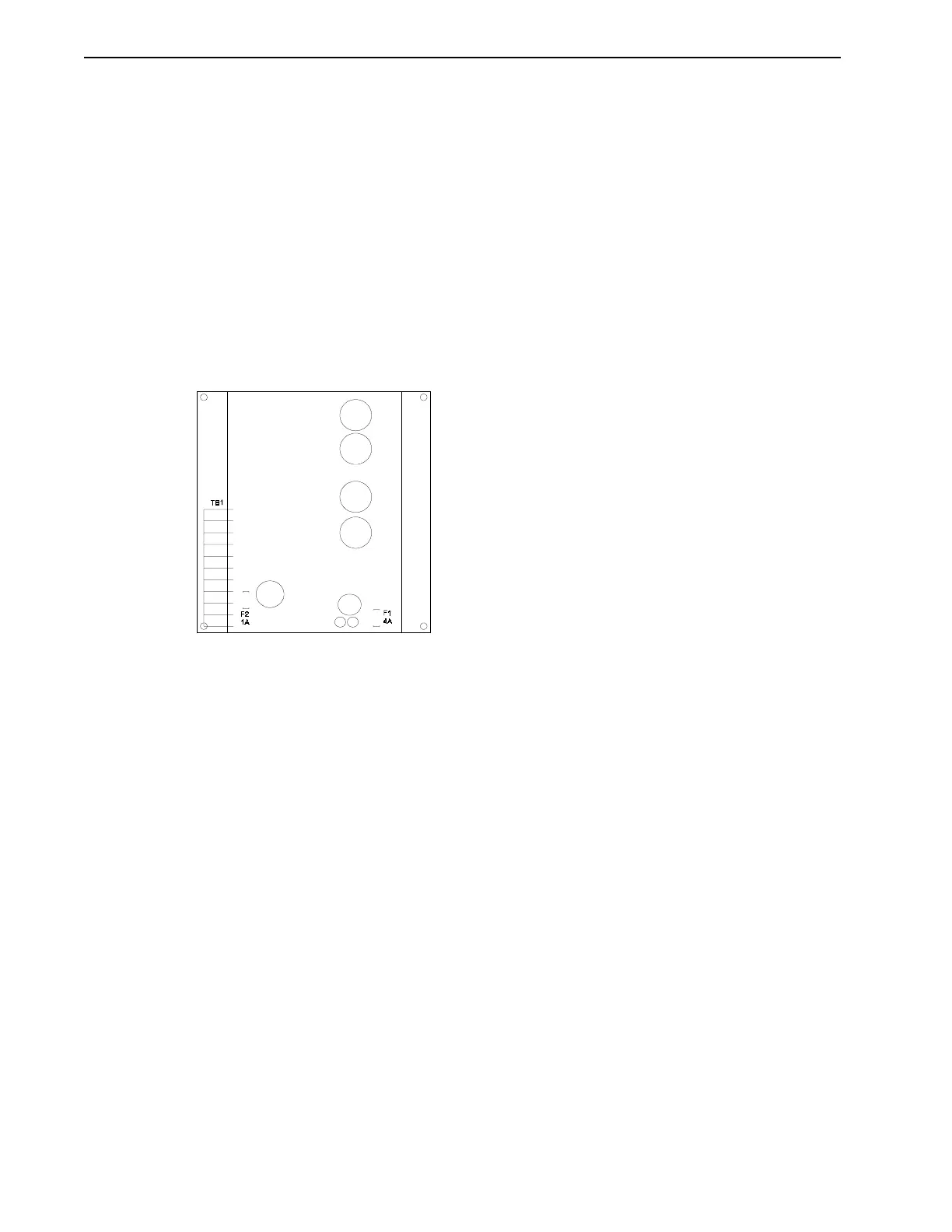
Checking and Replacing the Fuses
The DC Bus shunt fuse (F2) and the 24 VDC Auxiliary Power Input fuse (F1) are located on the
power amplifier board of the MAX-430.
To check and/or replace either fuse:
1. Measure voltages at TB1 pin 6 and pin 7 and at TB1 pin 9 and pin 10 to insure incoming
power is OFF. Make sure that the green READY LED is OFF. Remove the MAX-430
cover.
2. Remove the shunt fuse (F2) and/or AUX. Power Input fuse (F1) and test with an ohm-
meter.
3. Replace the blown fuse with the proper replacement. See Chapter 6, “Component
Ordering Information”.
4. Replace the MAX-430 cover.
Intro
F
IGURE
4.1
Location of Fuses