Installation 2-17
Instruction Manual
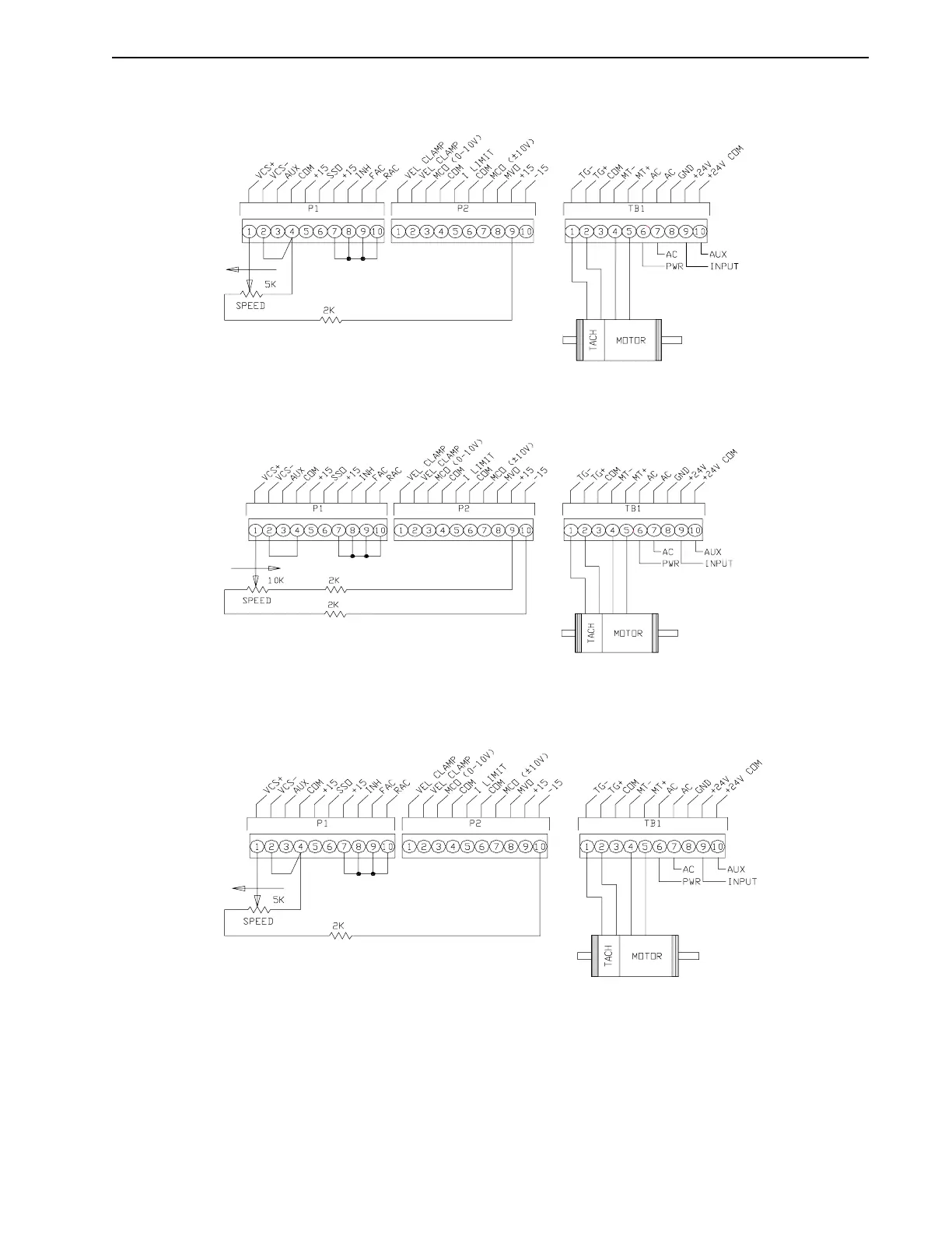
This diagram shows wiring and resistors needed when control in the clockwise direction only
is desired.
Bi-directional control is illustrated in the following diagram.
The following diagram shows wiring and resistors needed when control in the counterclockwise
direction only is desired.
Some applications may require the drive to run in torque mode. The following diagram shows
a suggested method for using the
±
15 volts on P2 pins 9 and 10 as a voltage source for the VCS
input. With positive voltage at VCS+ with respect to VCS-, there will be torque in the CW
direction. With negative voltage at VCS+ there will be torque in the CCW direction. The velocity
clamp must be jumpered. Tachometer feedback should not be used when in torque mode (cur-
rent mode).
Intro
F
IGURE
2.19
CW Remote VCS Control
Intro
F
IGURE
2.20
CW/CCW Remote VCS Control
Intro
F
IGURE
2.21
CCW Remote VCS Control