Installation 2-11
Instruction Manual
Connection
FAC: P1 pin 9
RAC: P1 pin 10
(Refer to “Internal Connections (FAC, RAC and INH)” below.)
Internal Connections (FAC, RAC and INH)
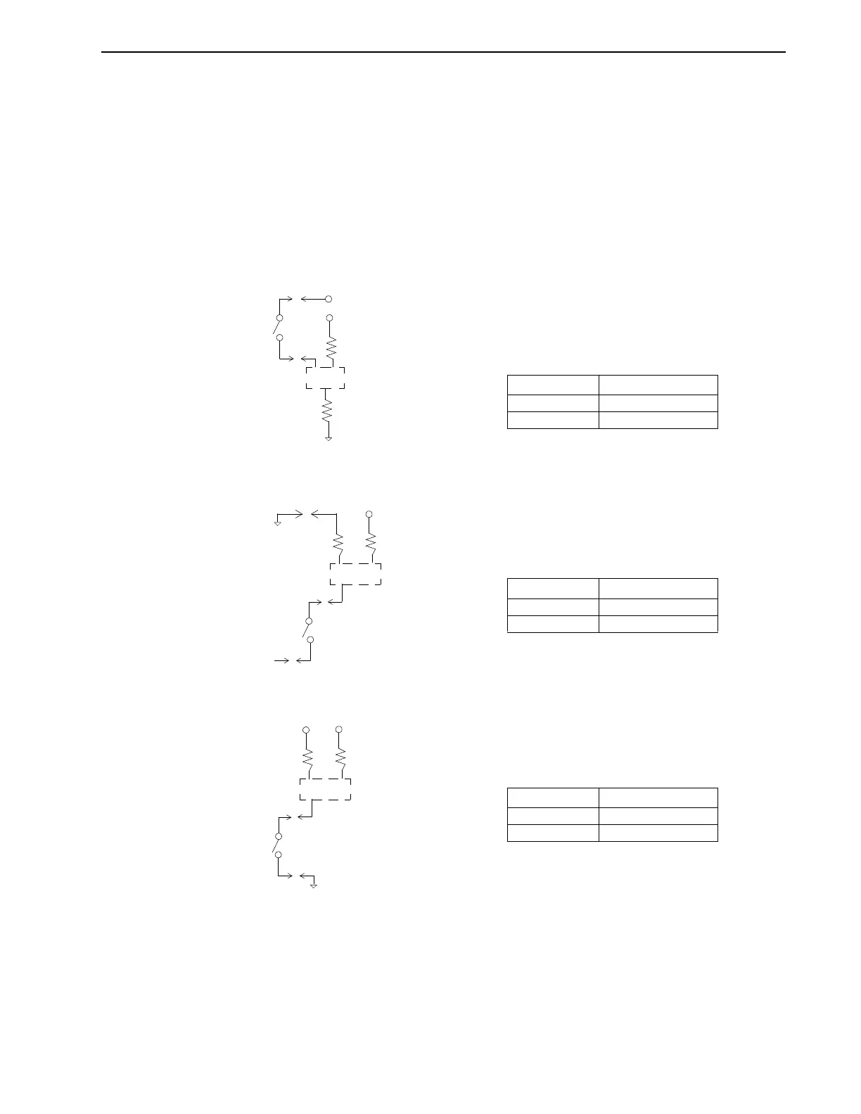
The following circuit diagrams apply to FAC, RAC and INH inputs, so that all three inputs must
operate in the same manner. See Figure 2.1 for a diagram of the jumper locations and refer to
the Figure 7.2 on page 7-2.
Sourcing opto’s using internal power is the factory setting.
Intro
F
IGURE
2.8
Sourcing Opto’s with Internal Power (P8A: pins 1-2 and P8: pins 1-2)
Intro
F
IGURE
2.9
Sourcing Opto’s with External Power (P8A: pins 2-3 and P8: pins 2-3)
Intro
F
IGURE
2.10
Sinking Opto’s with Internal Power (P8A: pins 2-3 and P8: pins 1-2)
Active High:
To enable the drive, or to release the forward or
reverse amplifier clamps, hold input at high volt-
age (P1-7).
Switch Status
Closed OK
Open Clamped
Opto
3.3k
1.0k
+15V
Unregulated +15VP1-7
INHIBIT P1-8,
FAC P1-9
or
RAC P1-10
+15V COM
Active High:
To enable the drive, or to release the forward or
reverse amplifier clamps, hold input at high volt-
age. External power must be supplied to P1-7.
Switch Status
Closed OK
Open Clamped
Opto
1.0k
+15V
+ 22-28 VDC
INHIBIT P1-8,
FAC P1-9
or
RAC P1-10
3.3k
COMMON
+ 22-28 VDC
Supply
P1-7
Active High:
To enable the drive, or to release the forward or
reverse amplifier clamps, hold input at common.
Switch Status
Closed OK
Open Clamped
Opto
1.0k
+15VUnregulated +15V
COM
INHIBIT P1-8,
FAC P1-9
or
RAC P1-10
3.3k
P1-4