4-4 Diagnostics/Troubleshooting
P/N 0013-1025-001 Rev F
Light Emitting Diodes
Power LED (Green)
The flyback power supply is monitored by this LED. Whenever power is applied to the drive,
this indicator will be on.
If any of the following conditions occur, the output stage will be disabled also.
To clear any fault, the Inhibit input must be switched to the disabled condition to reset the fault
latch.
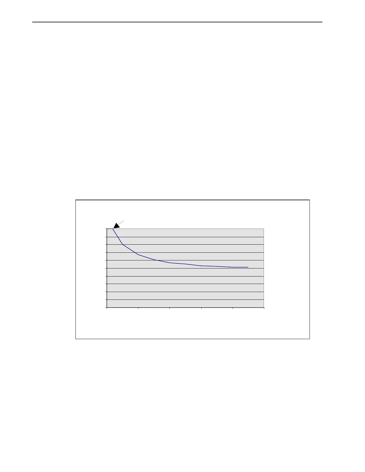
Figure 4.2 shows the approximate length of time that current exceeding average current can be
drawn through the drive before the drive faults.
T
ABLE
4.2
LED Fault Conditions
Fault LEDs (Red) Condition
O-Current This LED will turn on due to three conditions:
1
Short circuit overcurrent
2
Excessive avera
e current
see fi
ure below
3
FAC or RAC in an invalid state.
0.9mA < opto source/sink current < 1.4mA
O-Volt Bus overvolta
e
above 140 VDC
O-Temp Heat sink overtemperature
above 90ºC
Intro
F
IGURE
4.2
Excessive Current Timeout Diagram
Excessive Current Timeout
0
10
20
30
40
50
60
70
80
90
100
0 1020304050
Time (seconds)
% Peak Output Current
1.8 Sec.