Installation 2-13
Instruction Manual
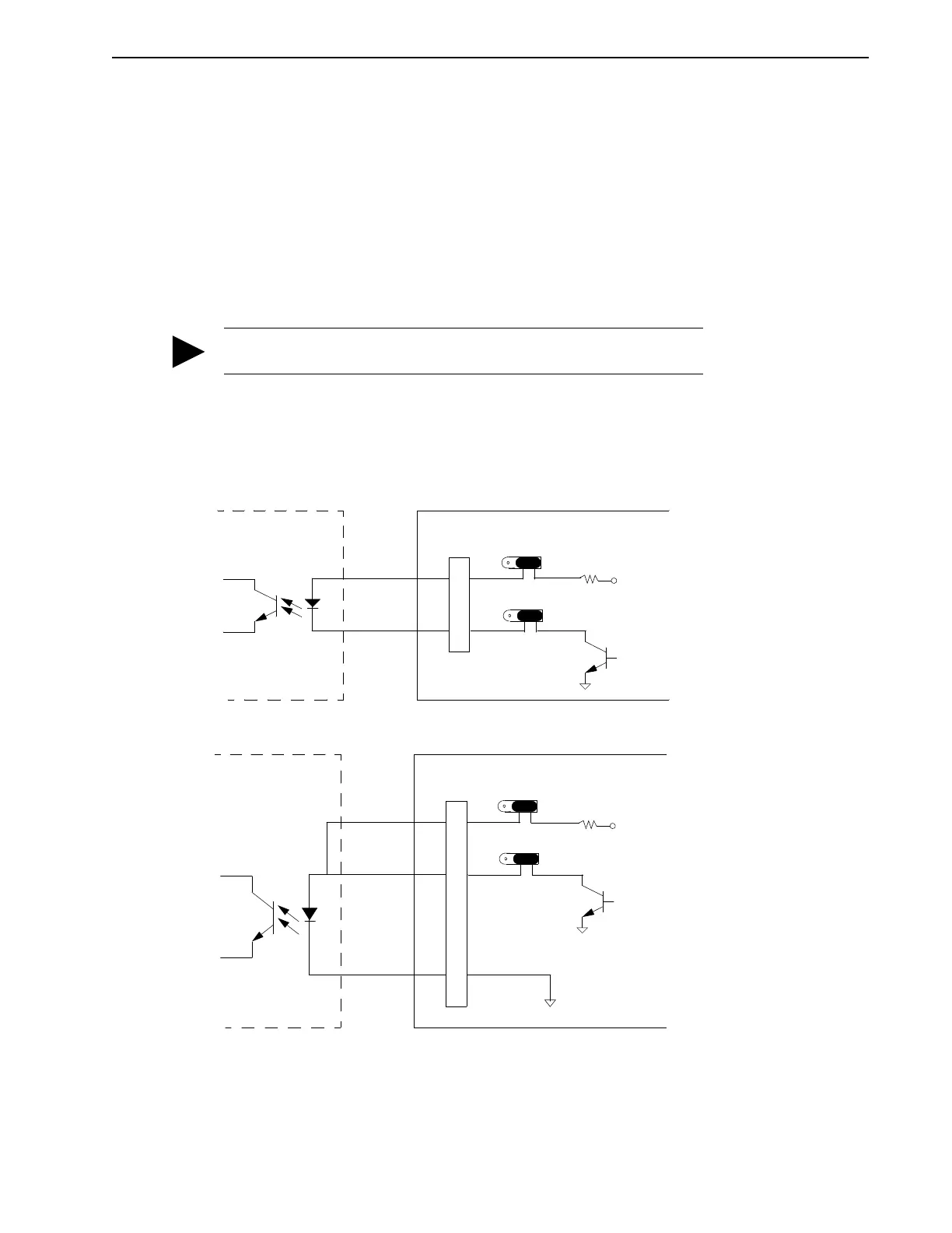
Connecting Outputs
System Status Output (SSO)
Function
This output signal provides information on the operational status of the MAX-430 drive. With
jumpers P9 and P9A in the SSO open collector output setting shown in the figures “SSO - Open
Collector Sourcing” and “SSO - Open Collector Sinking”, the SSO signal is assigned a logic level
“1” to indicate “drive ready” status. A logic level “0” indicates a detected fault condition (with
simultaneously inhibited output stage). With jumpers P9 and P9A in the appropriate settings
shown in the figure “SSO - Normally Closed Relay with Internal Power” the logic levels are the
opposite of the open collector logic levels. Refer to Figure 2.1.
If there is a fault, one of the red LEDs on the drive turns on to indicate which fault has occurred.
See “Light Emitting Diodes” on page 4-4.
Connection
P1 pins 5 and 6
(Refer to the following diagrams.)
TIP
The open collector configuration cannot be used with external power.
Intro
F
IGURE
2.12
SSO - Open Collector Sourcing
Intro
F
IGURE
2.13
SSO - Open Collector Sinking
1.0k
+15VDC
SSO
FAULT = (ON)
MAX-430 SERVO DRIVE
5
6
ON = FAULT
CUSTOMER
+15 VDC
SSO
CONTROLLER
(Sourcing I/O)
P1
1 2 3
P9A
1 2 3
P9
1.0k
+15VDC
SSO
FAULT = (ON)
MAX-430 SERVO DRIVE
5
6
ON = OK
CUSTOMER
+15 VDC
SSO
CONTROLLER
(Sinking I/O)
4
P1
COM
1 2 3
P9
1 2 3
P9A