2-2 Installation
P/N 0013-1025-001 Rev F
* Indicates Factory Setting
P8 2-3 External Opto Power Customer supplies power
24V
to opto’s on
FAC, RAC and INHibit inputs.
2-11
P8A 2-3 External Sourcin
Opto’s Opto’s are sourcin
inputs
pulled up to 24V
b
external power when true
.
NOTE
: External power polarit
connec-
tions define circuit as sourcin
.
2-11
P8A 2-3 External Sinkin
Opto’s Opto’s are sinkin
inputs
pulled down to
0V b
external power when true
.
NOTE
: External power polarit
connec-
tions define circuit as sinkin
.
2-12
P9 & P9A 1-2 SSO Rela
S
stem Status Output is controlled b
a
rela
2-13
2-3
∗
SSO Open Collector S
stem Status Output is controlled b
an
open collector transistor
2-13
Intro
F
IGURE
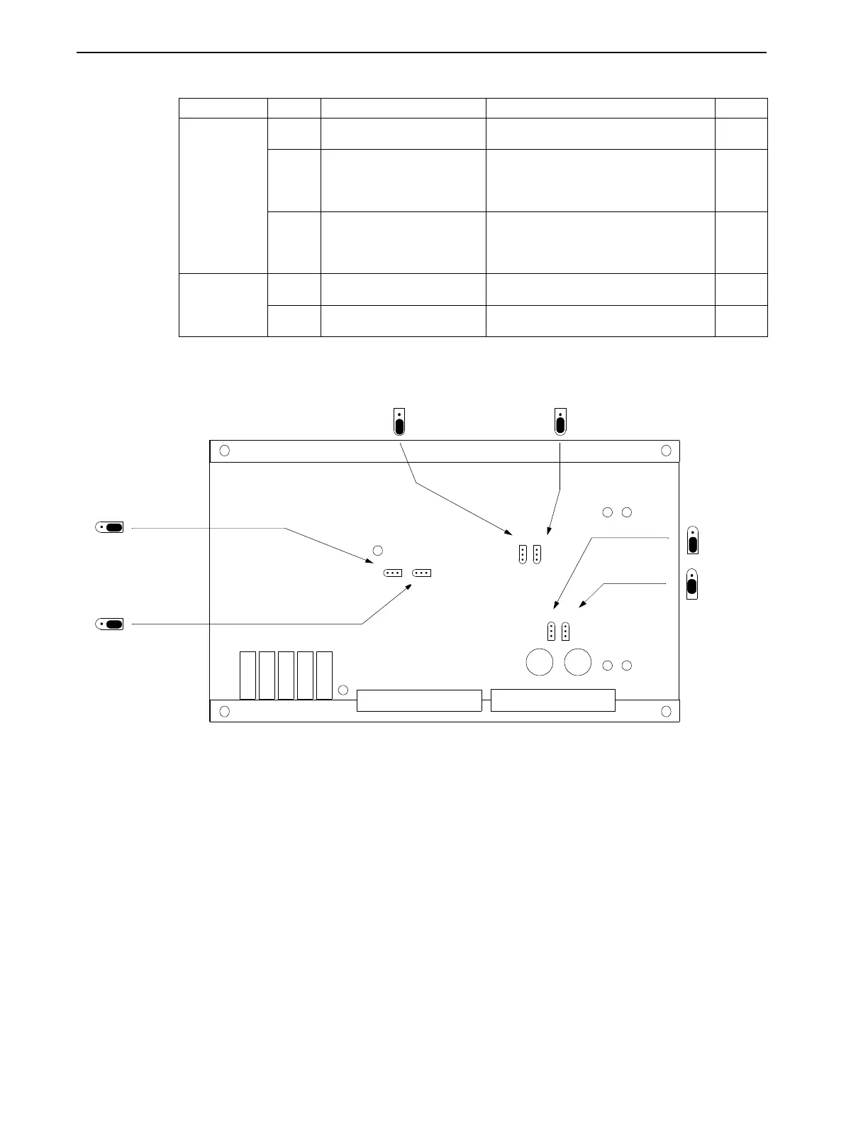
2.1
Jumper Locations
T
ABLE
2.1
Inputs and Outputs with Jumpers P6 through P9A
(continued)
Jumper Pins Position Operation Page
NOTE
: Figure depicts factory jumper settings. Refer to the “Internal Connections (FAC, RAC
and INH)” on page 2-11 for diagrams to connect externally powered opto’s.
123
VERR
EN INTG
+15V-15V
C22C21
P2
P1
ICMD
VCS
TAC H
COMP
BAL
ILIM
P6 P7
P8 P8A
P9 P9A
P7
2-3 = RAC DISABLE
123
P6
2-3 = FAC DISABLE
3
2
1
P8A
1-2 = SOURCING OPTO’S
1
2
3
P9A
1
2
3
P9
3
2
1
P8
1-2 = INTERNAL OPTO POWER
2-3 =
SSO OPEN
COLLECTOR
OUTPUT