34
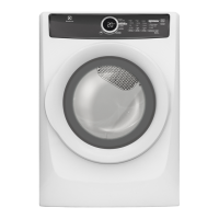
Step: 1
1. Remove the two
screws from bottom
view (See Fig. 1).
2. Remove the two
screws after opening
the Door (See Fig. 2)
3. Remove two screws
from top of Front
Panel (See Fig. 3).
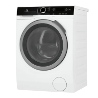
Step: 2
Lift the Front Panel upward and outward until it
releases from Side Panels (See Fig. 1). Do not remove
completely.
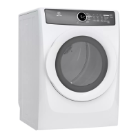
Step: 3
Unplug the Door Switch Connector and User Interface
Connector (See Fig. 1a and Fig. 1b) and remove the
Front Panel.
From Front Panel, you can access the following
components:
1. Door Switch
2. User Interface Board Assembly
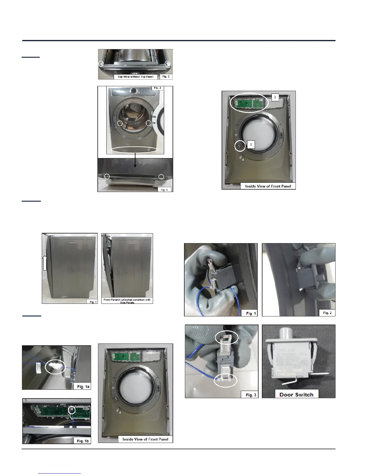
12. Front Panel Accessibility
12.1 Door Switch Accessibility
Press the snaps of the Door Switch (See Fig. 1) which
is located on the rear side of Front Panel, pull out the
switch from another side (See Fig. 2) and unplug the
connector from the Door switch (See Fig. 3).
 Loading...