-20-
Project #343
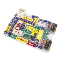
OBJECTIVE: To build a half wave rectifier circuit.
A rectifier changes an AC voltage into a DC voltage. A diode (D1) is
used because it allows current to flow in only one direction, for one
polarity of applied voltage. As the contacts open and close, it
generates an AC voltage across the transformer (T1) to the
secondary. We can measure the DC voltage on the transformer’s
secondary using a resistor (R4), a diode (D1), and an amp meter (M2).
Turn on the switch (S1), the LED lights as the meter points past the 5
scale.
Half Wave
Rectifier Circuit
OBJECTIVE: Measure the voltage using the
center-tap.
Use the circuit in project 343. Now see what
happens if you connect to the center-tap on
the secondary. Place the meter (M2) across
points A & B, then turn on the switch (S1).
The needle should be below the 5 scale, half
as much as project 343. As you use less
windings, the output decreases.
Half Wave
Rectifier
Circuit (II)
Project #344
OBJECTIVE: To see the voltage difference
between an LED and diode.
Use the circuit in project 343. Replace the
LED (D1) with the diode (D3) and turn on the
switch (S1). The needle deflects higher,
because the voltage across the diode is less
than the voltage across the LED.
LED vs. Diode
Project #345
OBJECTIVE: See how resistance affects
current.
Change the 10kΩ (R4) resistor to a 5.1kΩ
(R3) and turn on the switch (S1). You will see
that decreasing the resistance increases the
voltage across the meter (M2).
Current &
Resistance
Project #346