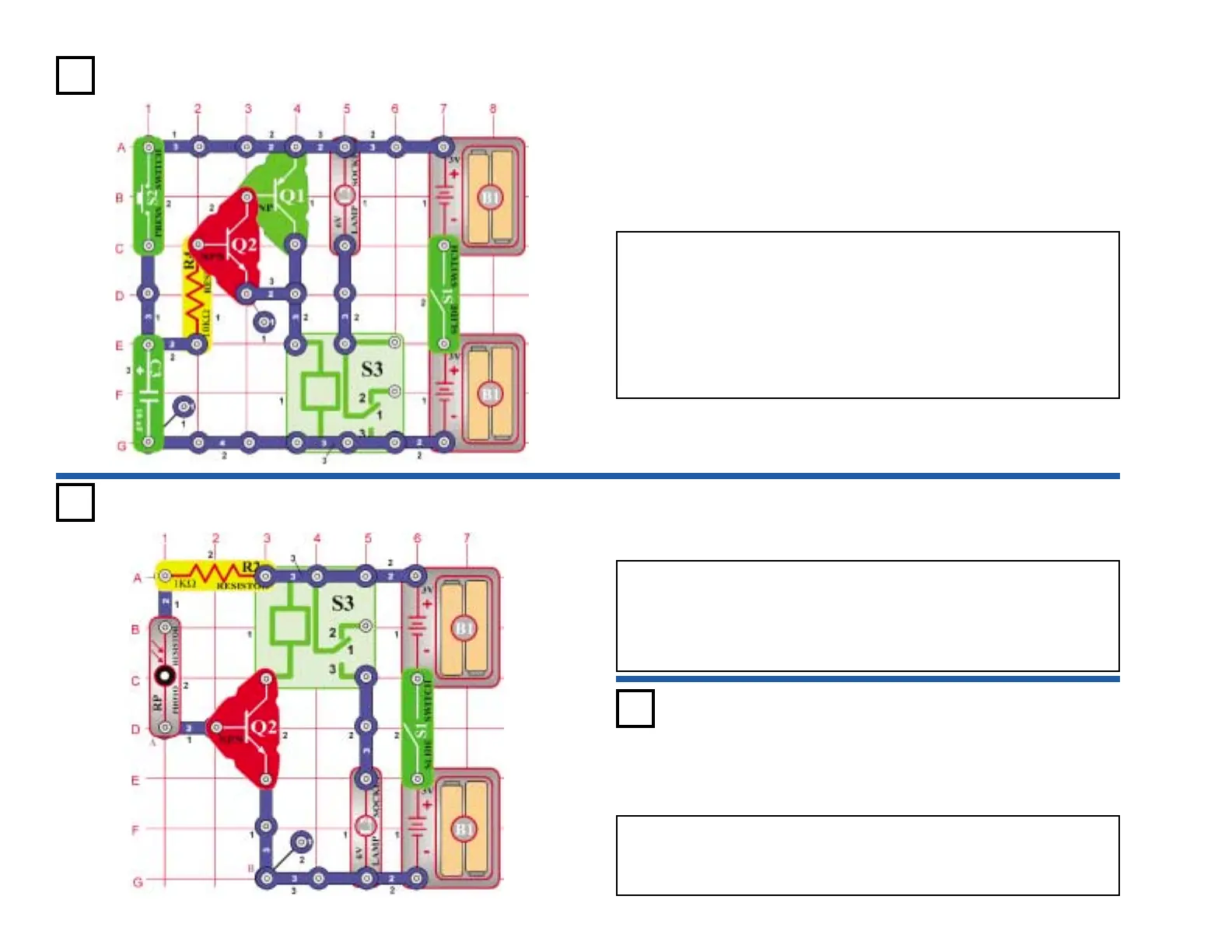
Project #355
OBJECTIVE: To use a photo resistor to control a relay.
Under normal light, the resistance of the photo resistor (RP) is low, allowing a voltage
at the base of the transistor (Q2). This turns the transistor on, connecting the relay (S3)
across the batteries, and the bulb (L2) lights. If the light decreases, the resistance
increases and the voltage to Q2 drops. If the voltage at Q2 decreases enough, the
transistor turns off.
Turn on the switch (S1) and the bulb lights. Now as you block the light from the photo
resistor, the bulb turns on and off.
Light-Controlled Relay
OBJECTIVE: Make a warning system that lights the bulb.
Replace the photo resistor (RP) with a 10kΩ resistor (R4). Connect the wire
to points A & B. As long as the wire is connected, the transistor (Q2) is off and
the relay (S3) and bulb (L2) are not powered. Disconnect the wire. The relay
contacts will switch and the bulb will light.
Bulb Alert Relay
Project #356
-23-
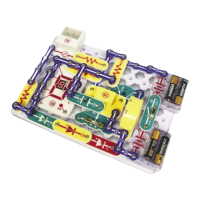
Project #354
OBJECTIVE: To build a manual timer using a transistor in
place of the relay.
This circuit is similar to project 342 except now two transistors are
used. Turn on the switch (S1) and hold down the press switch (S2).
The transistors (Q1 & Q2) turn on, the capacitor (C5) charges up, and
the bulb (L2) lights. When the press switch (S2) is released, the
capacitor discharges through the base, keeping the transistors on.
The transistors will turn off when the capacitor is almost discharged
(about 1 minute). The relay (S3) contacts will switch and the bulb will
turn off.
Transistor Timer