-53-
OBJECTIVE: To change the tone using the variable resistor.
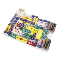
Set the variable resistor (RV) to the bottom position. Turn on the switch (S1) and you
should hear sound from the speaker (SP). Adjust the resistor to hear the different sounds.
Variable Oscillator
Project #477
OBJECTIVE: To change the tone using the variable resistor.
Variable Oscillator (II)
Project #478
Project #479
Use the circuit in project 477. Connect the
whistle chip (WC) across points B & C and
adjust the resistor (RV).
Variable Oscillator (III)
Project #480
OBJECTIVE: Show variations of project 477.
Variable Oscillator (IV)
Project #481
OBJECTIVE: Show variations of project 477.
Photo Variable Resistor
Use the circuit in project 477. Connect the whistle chip (WC) across points A & B
and adjust the resistor (RV). You should hear a higher tone. This is generated by
the whistle chip (WC).
Project #482
OBJECTIVE: Show variations of project 477.
Photo Variable Whistle
Chip Oscillator
Project #483
OBJECTIVE: Show variations of project 477.
Slow Adjusting
Tone
Project #484
OBJECTIVE: Show a variation of project 483.
Slow Adjusting
Tone (II)
Use the circuit in project 477. Connect the
whistle chip (WC) across points D & E and
adjust the resistor (RV).
Use the circuit in project 477.
Replace the 100kΩ
resistor (R5) with the photo resistor (RP). Wave
your hand over the resistor and the sound changes.
Adjust the resistor (RV) to make more sounds.
Use the circuit in project 477, remove the
speaker (SP). Make three more sounds by
placing the whistle chip (WC) across points, A
& B, B & C, and D & E.
Use the circuit in project 477. Place the 10µF
capacitor (C3) (+ towards the top) directly over the
.02µF capacitor (C1). A tone is generated once or
twice per second, depending on the resistor setting.
Use the circuit in project 483. Replace the 10µF
capacitor (C3) with the 100µF capacitor (C4) and the
tone is much slower. To make it even slower, replace
the 100µF capacitor (C4) with the 470µF capacitor (C5).
OBJECTIVE: Show variations of project 477.