-24-
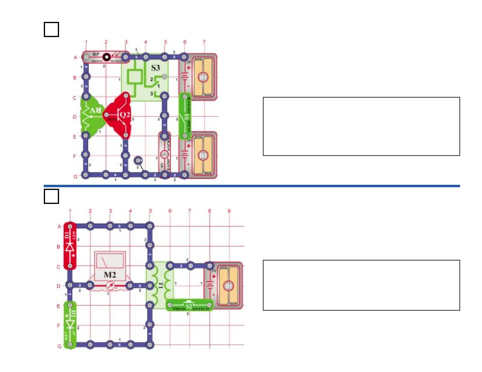
Project #357
OBJECTIVE: Build an adjustable light-controlled relay.
You can set the amount of light it takes to keep the bulb (L2) on by
adjusting the variable resistor (RV). Set the variable resistor to the top
position and turn on the switch. The bulb lights. Cover the photo
resistor (RP) and the bulb turns off. Set the variable resistor to
different positions and then cover the photo resistor. Note that only
the top half of the variable resistor affects the circuit. If you position it
below the middle, the bulb stays off.
Adjustable Light
Control
Project #358
OBJECTIVE: To demonstrate the properties of a transformer.
Pressing and releasing the press switch (S2) generates a DC current
on the secondary of the transformer (T1). The current lights the LEDs
(D1 & D2) and deflects the meter (M2) to the right. There are two
current paths as shown by the arrows. Placing the meter in series with
both current paths measures the total current. If you remove one LED,
the meter deflects half the amount.
Meter Deflection