-43-
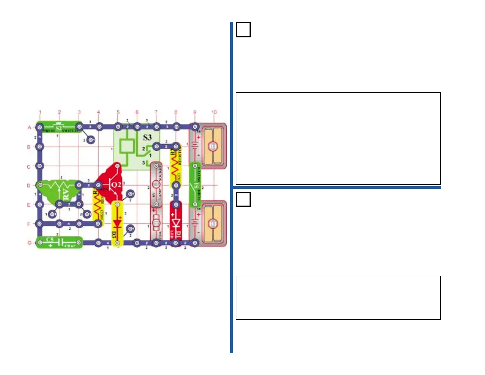
The length of time the motor (M1) runs depends on the position of the
variable resistor (RV). When the press switch (S2) is pressed, the 470µF
capacitor (C5) charges. As the press switch is released, C5 discharges
through the resistors R4 and RV, turning the transistor (Q2) on.
Transistor Q2 connects the relay (S3) to the batteries, the contacts
switch, and the motor (M1) spins. As the voltage decreases, Q2 will turn
off and the motor will stop spinning.
Setting RV to the right (large resistance) sets a long discharge time. To
the left, a short discharge time.
Turn on the switch (S1), the red LED (D1) lights. Now press and release
the switch (S2), the bulb lights and the motor spins.
Project #431
Time Delay
1-7 Seconds
OBJECTIVE: To build a time delay circuit.
Project #432
Time Delay
OBJECTIVE: To see how the capacitor value affects the time.
Use the circuit in project 431. Replace the 470µF capacitor (C5) with the
100µF capacitor (C4). Set the variable resistor (RV) to the far right, turn
on the switch (S1), then press and release the switch (S2). The motor
(M1) spins and bulb (L2) lights for about 3 seconds. Adjust the variable
resistor to the left for a much shorter time.