-55-
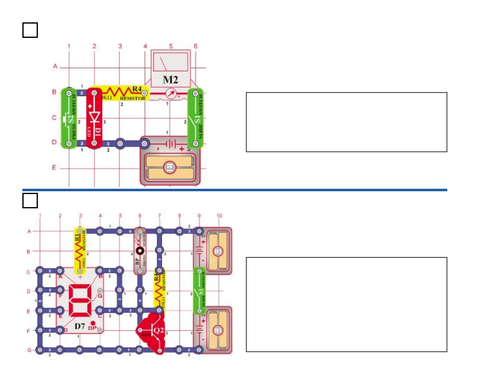
Project #487
OBJECTIVE: To measure the voltage drop across diodes.
Turn on the switch (S1) and the LED (D1) lights as the meter (M2)
deflects to the middle of the scale. The sum of the voltage drop across
each components equals the battery voltage. Bypass the LED by
pressing the switch (S2). The voltage across the 10kΩ resistor
increases, as shown by the meter deflecting more to the right. Replace
the red LED with the green LED (D2) and then the diode (D3), to see the
different voltage drops.
LED Voltage Drop
Project #488
OBJECTIVE: To make a circuit that indicates whether a door is
open or closed.
Using the photo resistor (RP) you can build a circuit that indicates if a
door is open or closed. When the door is open and light is present, the
letter “O” lights. When the door is closed and the room is dark, the letter
C lights.
The photo resistor turns the transistor (Q2) on or off, depending on the
amount of light in the room. When the transistor is on (light present),
segments B & C connect to the (–) side of the batteries and letter “O”
lights. When the room is dark, the transistor is off and the letter “C”
lights. Segments B & C are connected to the transistor.
Turn the switch (S1) on and the letter “O” should light. Cover the photo
resistor, simulating closing the door, and the letter “C” lights.
Open/Closed Door
Indicator