Elenco
TM
Electronics is not responsible for parts damaged due to incorrect wiring.
If you suspect you have damaged parts, you can follow this procedure to systematically
determine which ones need replacing:
1 - 20. Refer to project manuals 1 & 2 (projects 1-101, 102-305) for testing steps 1-20, then
continue below.
21. FM Module (FM): Build project #307, you should hear FM radio stations.
22. Meter (M1): Build the mini-circuit shown here, the meter (M2) should
deflect full scale.
23. Recording IC (U6): Build project 308. Make an 8 second recording, then listen to the three
prerecorded songs.
24. Relay (S3): Build project #353. Turn on the switch (S1) and you should hear a buzzing sound
from the relay.
25. Transformer (T1): Build the mini-circuit shown here.
Pressing the switch (S2) flashes the LED. Connect the
jumper wire to the CT point. Pressing the switch (S2)
flashes the LED.
26. Diode (D3): Build the mini-circuit shown here, the LED should light.
Reverse the direction of D3, the LED should not light now.
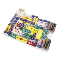
27. SCR (Q3): Build the mini-circuit shown here. Turn on the switch
(S1) and the motor should not spin. Press switch S2, the motor
should start spinning. Now open and close switch S1, the motor
should not spin.
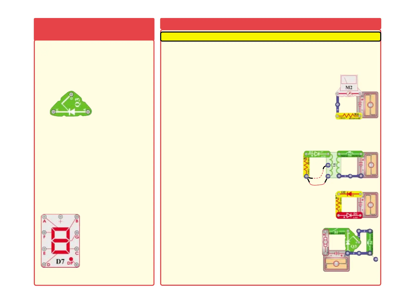
28. 7-Segment Display (D7): Build project #337. All segments light, displaying the number 8.
-4-
SCR (Q3) - An SCR is a three pin (anode, cathode
and gate) controlled silicon diode. Like a standard
diode, it permits current flow in only one direction. It
will only conduct in the forward direction when
triggered by a short pulse or steady voltage applied
to between the gate and cathode terminals.
A high
current may damage this part, so the current must
be limited by other components in the circuit.
The 7-segment display (D7) is found in many
devices today. It contains 7 LEDs that have been
combined into one case to make a convenient
device for displaying numbers and some letters.
The display is a common anode version. That
means that the positive leg of each LED is
connected to a common point which is the snap
marked +. Each LED has a negative leg that is
connected to one snap. To make it work you need
to connect the + snap to positive three volts. Then
to make each segment light up, connect the snaps
of each LED to ground. In the projects, a resistor is
always connected to the + snap to limit the current.
A high current may damage this part, so the
current must be limited by other components in
the circuit.
SCR:
A - Anode
K - Cathode
G - Gate
7-segment Display:
(+) - power from batteries
A - Segment A
B - Segment B
C - Segment C
D - Segment D
E - Segment E
F - Segment F
G - Segment G
DP - Decimal Point
See project 337 for example
of proper connections.
MORE Advanced Troubleshooting (Adult supervision
MORE About Your Snap
Circuits Parts (continued)