ELIS PLZEŇ a. s., Luční 425/15, 301 00 Plzeň, Czech Republic, Phone: +420/377 517 711, Fax: +420/377 517 722 Es90420K/c
5. METER APPLICATION RULES
The compact version of flowmeter is intended only for environments without occurrence of condensation and
where media temperature does not exceed +50 °C (122 °F).
5.1. Sensor placement in piping
No chemical injection or batching unit (such as chlorine compound injector) should be located at sensor’s
inlet. The insufficient homogeneity of the flowing liquid may affect the flow rate values indicated by the meter.
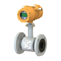
The meter performance will be the best if the liquid flow in the piping is well stabilised; therefore it is
necessary to observe specific rules for the sensor placement in piping. In the contact planes between the
sensor and the adjoining piping sections shall be no edges as these would cause flow turbulence. Make sure
that straight piping sections are provided before and after the sensor; their required length is proportional to
the inner diameter of piping.
If more than one flow-disturbing element such as pipe bend or fitting are located near the sensor, the
required length of straight piping section on the sensor side concerned should be multiplied by the quantity
of such elements.
As required by clause 4.2.1 of standard EN 29104, the inner diameter of the connected pipe shall not differ
by more than 3% from that of the sensor.
In the cases of bi-directional flow rate measurement, the same conditions concerning flow stability shall be
met at sensor’s input and output.
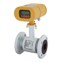
Required straight piping sections Pipe narrowing
Where the pipe size is larger than that of the meter
sensor, it is necessary to use conical reduction pieces
with the angle of taper not exceeding 15° (see the
picture). For a bi-directional flow measurement, the
minimum length of straight piping sections on both
sides is 5 DN. At horizontal sensor installations, to
prevent the occurrence of air bubbles, use
eccentrically-fitted reduction pieces (see standard
EN ISO 6817).
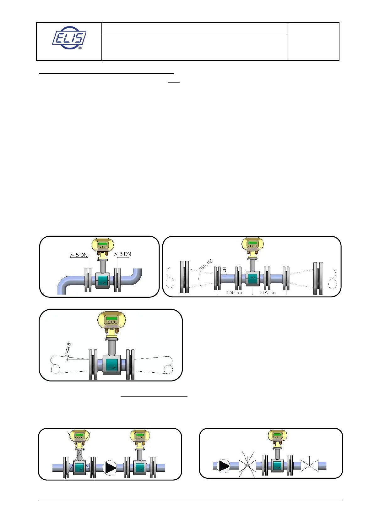
Pipe narrowing sections with angles not exceeding 8° can be taken for straight sections.
Where the liquid is pumped into the piping, the flow sensor shall always be placed at the outlet side of the
pump to prevent under pressure in the piping which might damage the sensor. The required length of the
straight piping section between the pump and sensor is at least 25 DN.
Pump in the piping Closing valve in the piping
 Loading...