ELIS PLZEŇ a. s., Luční 425/15, 301 00 Plzeň, Czech Republic, Phone: +420/377 517 711, Fax: +420/377 517 722 Es90420K/c
Content
1. INTRODUCTION ............................................................................................................................................5
2. MEASUREMENT PRINCIPLE .......................................................................................................................5
3. TECHNICAL DESCRIPTION .........................................................................................................................6
3.1. GENERAL DESCRIPTION ............................................................................................................................................... 6
3.2. METER DESIGN........................................................................................................................................................... 6
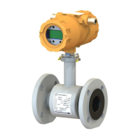
3.2.1. Remote version ................................................................................................................................................ 6
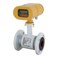
3.2.2. Compact version .............................................................................................................................................. 7
3.2.3. Protection of the flow meters against unauthorised intervention ...................................................................... 8
4. TECHNICAL PARAMETERS.........................................................................................................................9
4.1. FLOW SENSOR............................................................................................................................................................ 9
4.1.1. Selection of correct sensor size........................................................................................................................ 9
4.1.2. Operating pressure of measured liquid .......................................................................................................... 11
4.1.3. Selection of electrode material....................................................................................................................... 12
4.1.4. Selection of sensor tube lining ....................................................................................................................... 12
4.1.5. Compact and remote version ......................................................................................................................... 12
4.1.6. Dimensions of flanged sensor........................................................................................................................ 13
4.1.8. Sensor specifications ..................................................................................................................................... 16
4.2. TRANSMITTER HOUSING............................................................................................................................................. 17
4.2.1. Transmitter specifications............................................................................................................................... 17
5. METER APPLICATION RULES ................................................................................................................. 18
5.1. SENSOR PLACEMENT IN PIPING................................................................................................................................... 18
5.2. SENSOR GROUNDING ................................................................................................................................................ 20
6. FLOWMETER INSTALLATION AND COMMISSIONING.......................................................................... 21
6.1. SENSOR INSTALLATION.............................................................................................................................................. 21
6.2. ELECTRIC CONNECTION OF FLOWMETER...................................................................................................................... 22
6.2.1. Connection to power supply........................................................................................................................... 22
6.2.2. Output signal connections.............................................................................................................................. 22
6.3. INTERCONNECTION OF SENSOR AND TRANSMITTER (REMOTE VERSION)........................................................................... 23
6.4. INTERCONNECTION OF SENSOR AND TRANSMITTER (REMOTE VERSION WITH IP 68).......................................................... 23
6.5. COMMISSIONING....................................................................................................................................................... 23
6.5.1. The ECONOMIC version................................................................................................................................ 23
6.5.2. The COMFORT version ................................................................................................................................. 23
6.5.3. Operating data ............................................................................................................................................... 24
6.5.3.1. Display formats of aggregate values....................................................................................................... 26
6.5.3.2. Data reset ............................................................................................................................................... 26
7. CONFIGURATION ...................................................................................................................................... 27
7.1. BASIC MENU CONFIGURATION..................................................................................................................................... 28
7.1.1. Displayed data ............................................................................................................................................... 28
7.1.2. Number of samples ........................................................................................................................................ 29
7.1.3. Analog output................................................................................................................................................. 30
7.1.4. Output functions ............................................................................................................................................. 33
7.1.5. Electrode cleaning.......................................................................................................................................... 39
7.1.6. Serial line ....................................................................................................................................................... 40
7.1.7. Production data .............................................................................................................................................. 42
7.1.8. Dose setting ................................................................................................................................................... 44
7.1.9. Zero setting .................................................................................................................................................... 44
7.1.10. 100 per cent ................................................................................................................................................. 45
7.1.11. Exit ............................................................................................................................................................... 45
7.2. THE PARAMETER SETTING MENU................................................................................................................................ 47
7.3. THE PRODUCTION DATA MENU ................................................................................................................................... 48
8. ERROR REMOVAL AND METER REPAIR PROCEDURES..................................................................... 49
8.1. REPLACEMENT PC BOARDS .............................................................................................................................. 49
8.2. PROGRAM AND SIMULATION SOFTWARE ........................................................................................................ 49
8.3. FLOWMETER REPAIR PROCEDURE .................................................................................................................. 49
8.3.1. KV 1.0 Fixture for checking the meter outputs ............................................................................................... 53
 Loading...