Design, Assembly and Service Manual
Electromagnetic flowmeter FLONET FN20xx.1
ELIS PLZEŇ a. s., Luční 425/15, 301 00 Plzeň, Czech Republic, Phone: +420/377 517 711, Fax: +420/377 517 722 Es90420K/c
8.3.2.2. Checking the sensor condition fitted into piping and flooded with a measured liquid
The sensor grounding electrode is connected to the piping or grounding rings.
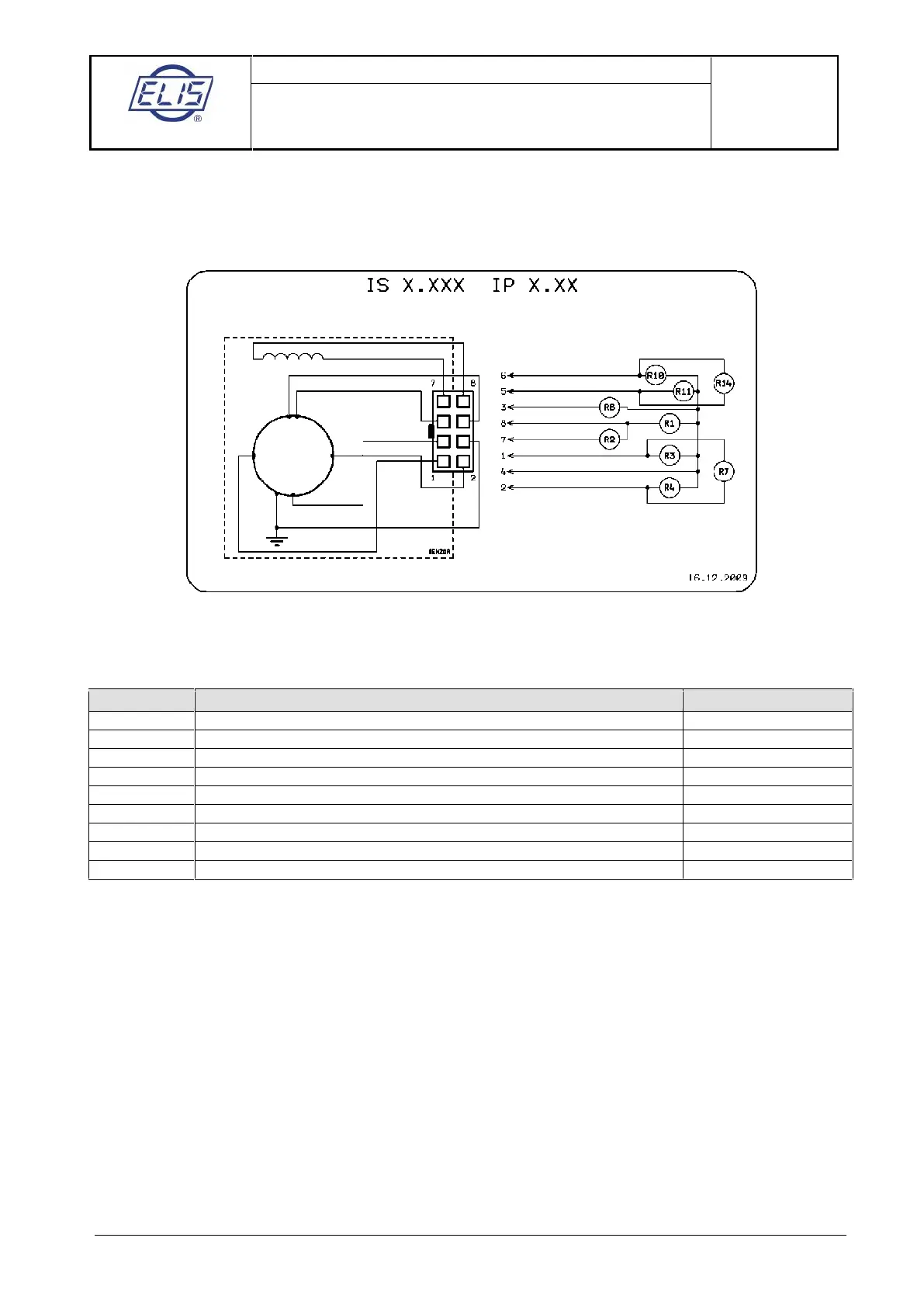
Schematic diagram: a particular sensor need not include all the depicted electrodes
Example: Measurement of R1. Connect Ohm-meter to connector pins 8 and 4 and measure resistance. Then
exchange the Ohm-meter leads and measure resistance again. Calculate the average value of the two
measurements and enter it as “Measured Value” into the table below.
Coil to sensor body insulation resistance (>2MΩ)
Excitation coil resistance (36 to 44Ω)
Liquid resistance between measuring electrode and sensor body
Liquid resistance between measuring electrode and sensor body
Liquid resistance between measuring electrodes
Liquid resistance between grounding electrode and sensor body
Liquid resistance between dry-condition electrode and sensor body
Liquid resistance between dry-condition electrode and sensor body
Liquid resistance between dry-condition electrodes
Comments:
If the electrodes indicating the not fully flooded (dry) piping condition are not included in the sensor
configuration, connector pins 5 and 6 are shorted and parameters R10 and R11 need not be measured. The
R14 measurement shall indicate a short-circuit condition.
If the grounding electrode is missing, connector pin 3 remains unconnected and parameters R8 need not be
measured.
 Loading...