Design, Assembly and Service Manual
Electromagnetic flowmeter FLONET FN20xx.1
ELIS PLZEŇ a. s., Luční 425/15, 301 00 Plzeň, Czech Republic, Phone: +420/377 517 711, Fax: +420/377 517 722 Es90420K/c
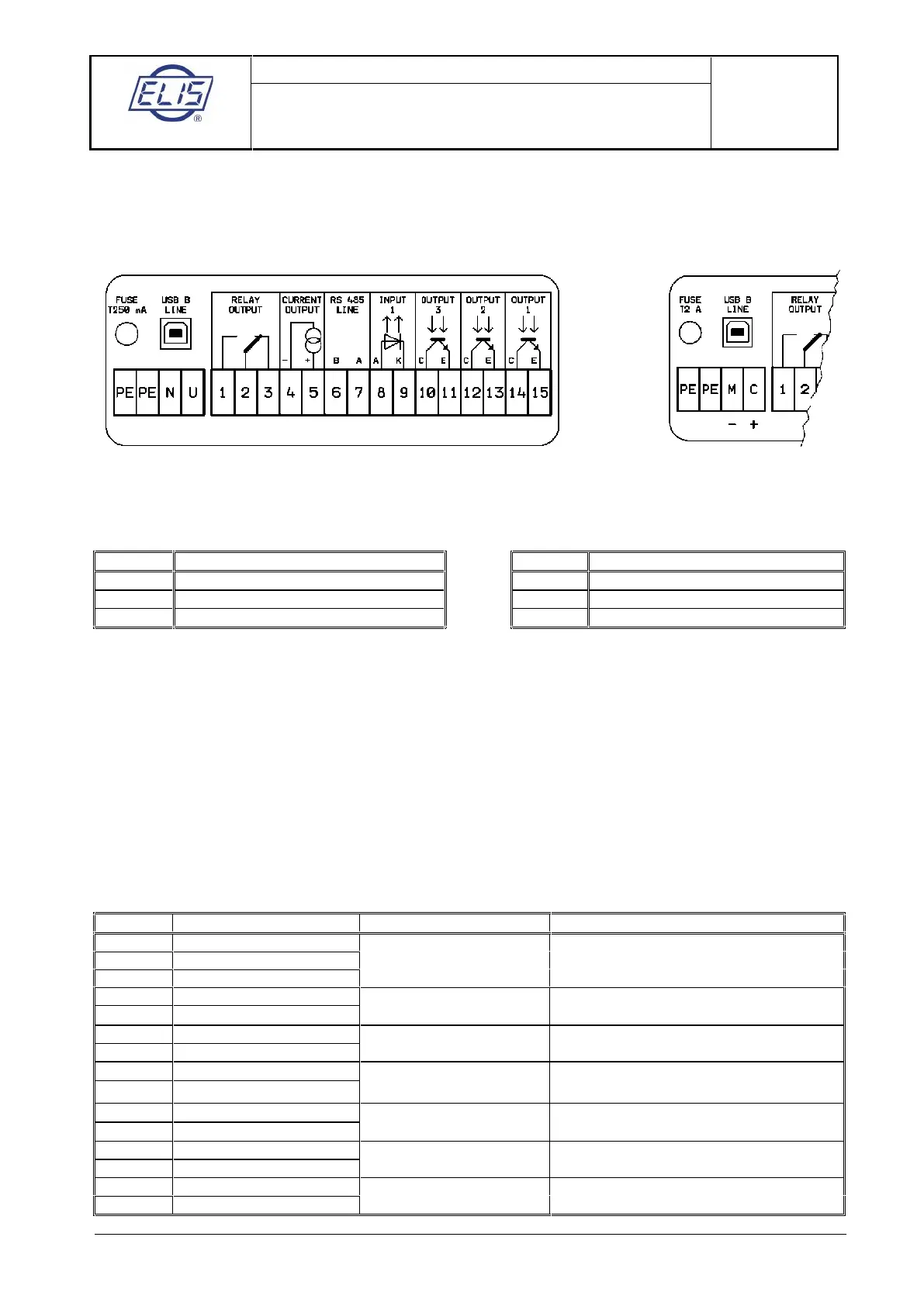
6.2. Electric connection of flowmeter
The terminals for connecting the cables can be accessed upon removal of a cover at the rear part of the
housing of transmitter. The cover is held by six socket-head bolts. A schematic diagram of connection is
shown at the inner side of the cover.
Examples of labels showing power supply (line voltage or 24VDC source) and meter signal interconnection
6.2.1. Connection to power supply
24V 115V 230V/AC/50 ÷ 60Hz
To connect the power source, use a standard cable of three conductors of square section not exceeding 3 x
1.5mm
2
. For ambient temperatures over 50 °C (122 °F), use a cable with rated operating temperature of at
least 90°C. The housing’s cable glands will only accommodate cables with outer diameter between 4 and
8mm. Use of any other cable would disturb the integrity of the IP 67 box.
The grounding conductor shall be longer than both the phase and neutral conductors. This is a safety
requirement as in the case of loosening the cable clamping in the gland, the grounding conductor shall be
the last to be disconnected from the terminal (see clause 6.10.2.2. of standard EN 61010-1).
The power supply line shall be protected by an overcurrent circuit breaker. A seal should be applied on the
breaker to prevent unauthorised tampering. The transmitter has no independent power switch. The
recommended rating of the overcurrent circuit breaker is 4 to 6A.
6.2.2. Output signal connections
Optocoupler insulated contact
Current output (optional)
Active output, max. loading (Rz) 1,000Ω.
No external power source needed.
To be directly connected
to communication line
Dosing (optional)
Binary input 1
Optocoupler collector (+)
Dosing (optional)
Binary output 3
Passive output requires external power
source and loading resistor
Optocoupler collector (+)
Passive output requires external power
source and loading resistor
Passive output requires external power
source and loading resistor
 Loading...