Design, Assembly and Service Manual
Electromagnetic flowmeter FLONET FN20xx.1
ELIS PLZEŇ a. s., Luční 425/15, 301 00 Plzeň, Czech Republic, Phone: +420/377 517 711, Fax: +420/377 517 722 Es90420K/c
8.3.2. Checking the sensor condition (compact version)
To check the sensor condition, dismantle the transmitter so as to gain access to the sensor connector.
Proceed as follows:
Remove the cover at the rear side of the transmitter housing. The cover is held in position by means of six
socket screws. With the cover removed, loosen and remove two RSK pin nuts using size 5 Alien wrench.
Then the front panel can be lifted off (mind the flat keypad cable). Disconnect the keypad. Pull out the
electronic block including the FNA5, FNP5 and FNZ5 boards by some 20mm, disconnect the connector of
the flow sensor from the analog board FNA5 and remove the block from the unit box. When reassembling
the unit, proceed in reverse order of the above steps.
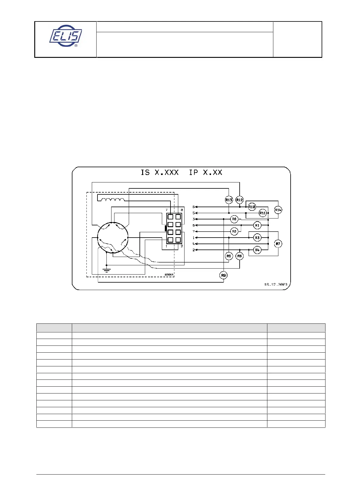
8.3.2.1. Measurements to be performed on sensor with no liquid inside (the lining is dry)
Schematic diagram: a particular sensor need not include all the depicted electrodes
Example: Measurement of R1. Connect Ohm-meter to connector pins 8 and 4 and measure resistance. Then
exchange the Ohm-meter leads and measure resistance again. Calculate the average value of the two
measurements and enter it as “Measured Value” into the table below.
Coil to sensor body insulation resistance (>2M
Ω)
Excitation coil resistance (36 to 44
Ω)
Measuring electrode to sensor body insulation resistance (>2M
Ω)
Measuring electrode to sensor body insulation resistance (>2M
Ω)
Measuring electrode to connector connection (short circuit)
Measuring electrode to connector connection (short circuit)
Insulation resistance between measuring electrodes (>2M
Ω)
Grounding electrode to sensor body insulation resistance (>2M
Ω)
Grounding electrode to connector connection (short circuit)
Dry-condition electrode to sensor body insulation resistance (>2MΩ)
Dry-condition electrode to sensor body insulation resistance (>2M
Ω)
Dry-condition electrode to connector connection (short circuit)
Dry-condition electrode to connector connection (short circuit)
Insulation resistance between dry-condition electrodes (>2M
Ω)
Note:
If the electrodes indicating the not fully flooded (dry) piping condition are not included in the sensor
configuration, connector pins 5 and 6 are shorted and parameters R10 through to R13 need not be
measured. The R14 measurement will indicate a short-circuit condition.
If the grounding electrode is missing, connector pin 3 remains unconnected and parameters R8 and R9 need
not be measured.
 Loading...