Design, Assembly and Service Manual
Electromagnetic flowmeter FLONET FN20xx.1
ELIS PLZEŇ a. s., Luční 425/15, 301 00 Plzeň, Czech Republic, Phone: +420/377 517 711, Fax: +420/377 517 722 Es90420K/c
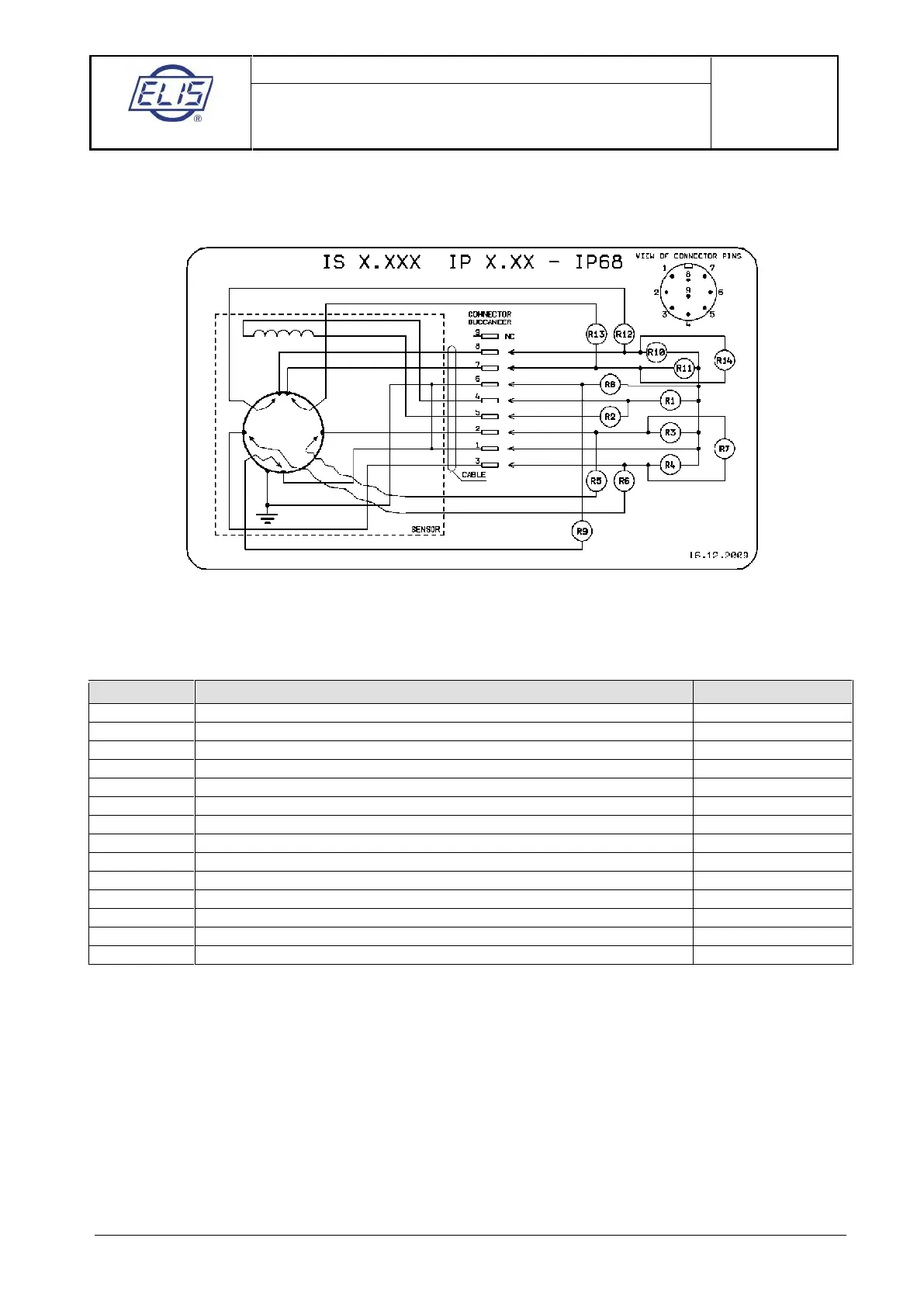
8.3.4. Checking the sensor condition (remote transmitter with IP68 housing)
The sensor and connecting cable are to be checked simultaneously. On the side of the transmitter, the
cable is terminated by a 9-pin Buccaneer connector via which all measurements shall be done.
Example: Measurement of R1. Connect Ohm-meter to connector pins 4 and 1 and measure resistance. Then
exchange the Ohm-meter leads and measure resistance again. Calculate the average value of the two
measurements and enter it as “Measured Value” into the table below.
Coil to sensor body insulation resistance (>2M
Ω)
Excitation coil resistance (36 to 44
Ω)
Measuring electrode to sensor body insulation resistance (>2M
Ω)
Measuring electrode to sensor body insulation resistance (>2M
Ω)
Measuring electrode to connector pin connection (short circuit)
Measuring electrode to connector pin connection (short circuit)
Insulation resistance between measuring electrodes (>2M
Ω)
Interconnection of connector pins 1 and 6 (short circuit)
Grounding electrode to sensor body connection (short circuit)
Dry-condition electrode to sensor body insulation resistance (>2M
Ω)
Dry-condition electrode to sensor body insulation resistance (>2M
Ω)
Dry-condition electrode to connector pin connection (short circuit)
Dry-condition electrode to connector pin connection (short circuit)
Insulation resistance between dry-condition electrodes (>2M
Ω)
Note:
If the electrodes indicating the not fully flooded (dry) piping condition are not included in the sensor
configuration, connector pins 7 and 8 are free and resistances R10 through to R14 need not be measured.
If the grounding electrode is missing, parameter R9 need not be measured either.
 Loading...