Design, Assembly and Service Manual
Electromagnetic flowmeter FLONET FN20xx.1
ELIS PLZEŇ a. s., Luční 425/15, 301 00 Plzeň, Czech Republic, Phone: +420/377 517 711, Fax: +420/377 517 722 Es90420K/c
8.3.3. Checking the sensor condition (remote transmitter with IP67 housing)
To check the condition of the meter sensor, remove the lid on the sensor terminal housing. Disconnect the
cable to the associated transmitter and perform the required sensor parameter measurements. In case of the
IP67 design version, the terminals are readily accessible. With IP68 design, the terminals including the cable
end are sealed with packaging compound and cannot be accessed.
8.3.3.1. Measurements to be performed on sensor with no liquid inside (the lining is dry)
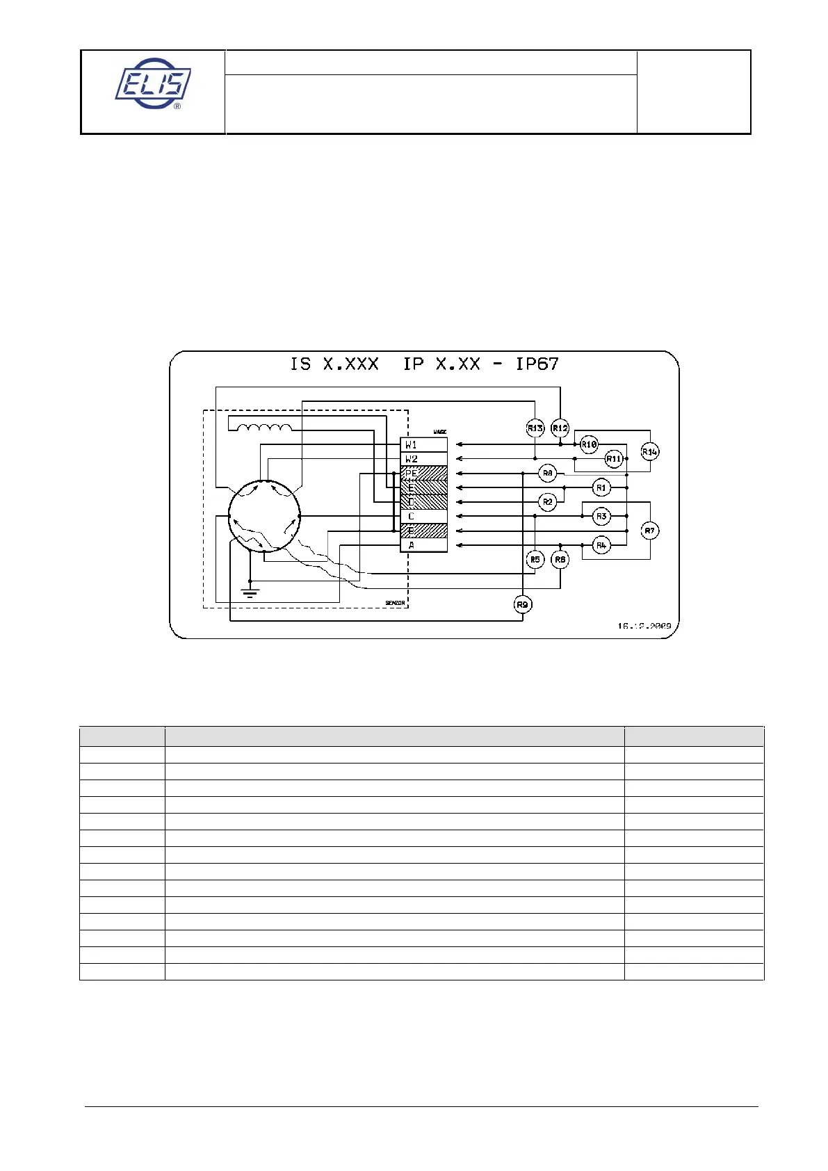
Schematic diagram: a particular sensor need not include all the depicted electrodes
Example: Measurement of R1. Connect Ohm-meter to the terminals E a B and measure resistance. Then
exchange the Ohm-meter leads and measure resistance again. Calculate the average value of the two
measurements and enter it as “Measured Value” into the table below.
Coil to sensor body insulation resistance (>2M
Ω)
Excitation coil resistance (36 to 44
Ω)
Measuring electrode to sensor body insulation resistance (>2M
Ω)
Measuring electrode to sensor body insulation resistance (>2M
Ω)
Measuring electrode to Terminals connection (short circuit)
Measuring electrode to Terminals connection (short circuit)
Insulation resistance between measuring electrodes (>2M
Ω)
Interconnection between Terminals points PE and B (short circuit)
Grounding electrode to sensor body connection (short circuit)
Dry-condition electrode to sensor body insulation resistance (>2M
Ω)
Dry-condition electrode to sensor body insulation resistance (>2M
Ω)
Dry-condition electrode to Terminals connection (short circuit)
Dry-condition electrode to Terminals connection (short circuit)
Insulation resistance between dry-condition electrodes (>2M
Ω)
Note:
If the electrodes indicating the not fully flooded (dry) piping condition are not included in the sensor
configuration, terminal pins W1 and W2 are free and resistances R10 through to R14 need not be measured.
If the grounding electrode is missing, parameter R9 need not be measured.
 Loading...