The Trex unit can be connected at various point along the loop to measure current.
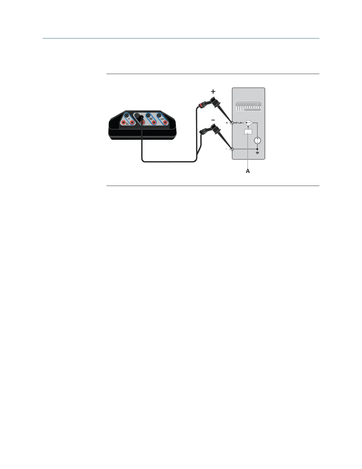
Example connection for measuring currentFigure 4-18:
A. Analog output.
2. In the Loop Diagnostics application, view the measured current at the top of the
screen.
4.11.3 Simulate a transmitter on an externally-powered loop
for a loop check
The Loop Diagnostics application can control current to simulate a 2-wire transmitter on
an externally-powered loop. In this setup, the digital control system is powering the
current loop and the Trex unit is controlling the current that is input into the digital control
system.
Procedure
1. Connect the lead set to the HART terminals on the Trex unit and to the powered
4-20 mA current loop.
Loop Diagnostics application
146 User Guide

 Loading...

