18 100-412-196 REV. 06
Table 2.1 Front Panel Controls and Indicators
Reference Description
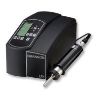
LCD
The LCD allows for easy navigation, configuration, and for
communicating weld settings and results.
The LCD is divided into three sections:
The Top section is used to highlight the current weld mode when running
and to select the weld mode when configuring the system.
The Middle section is used to indicate available parameters for each weld
mode and to indicate which parameter corresponds with the value
shown on the LCD bottom section.
The Bottom section is used to display and edit parameter and register
values; to select presets and registers; to display real time weld data;
and to indicate alarms or that a weld is in progress.
For a detailed description of the display icons refer to Table 2.2.
Up/Down Arrow Keys
Press Up/Down Arrow keys to select weld modes and registers, and to
set register and parameter values. Digit selection is circular, for each
digit pressing Up Arrow key from 9 takes you to 0. Pressing Down from
0 takes you to 9.
Left/Right Arrow Keys
Press Left/Right Arrow keys to select weld modes and to move
horizontally through digits when setting parameter or register values.
Enter Key
Press Enter key to accept weld mode, weld parameters, register and
preset selection; and to accept register and preset values.
Save Preset Key
Press the Save Preset key to select a memory location to save the
current weld settings. For more information on saving weld presets see
6.6 Save/Recall Weld Preset.
Recall Preset Key
Press the Recall Preset key to select a weld preset from available
memory locations. For information on saving presets see 6.6 Save/
Recall Weld Preset.
 Loading...


