1.2.1 T-Slot Transducer assembly and mount
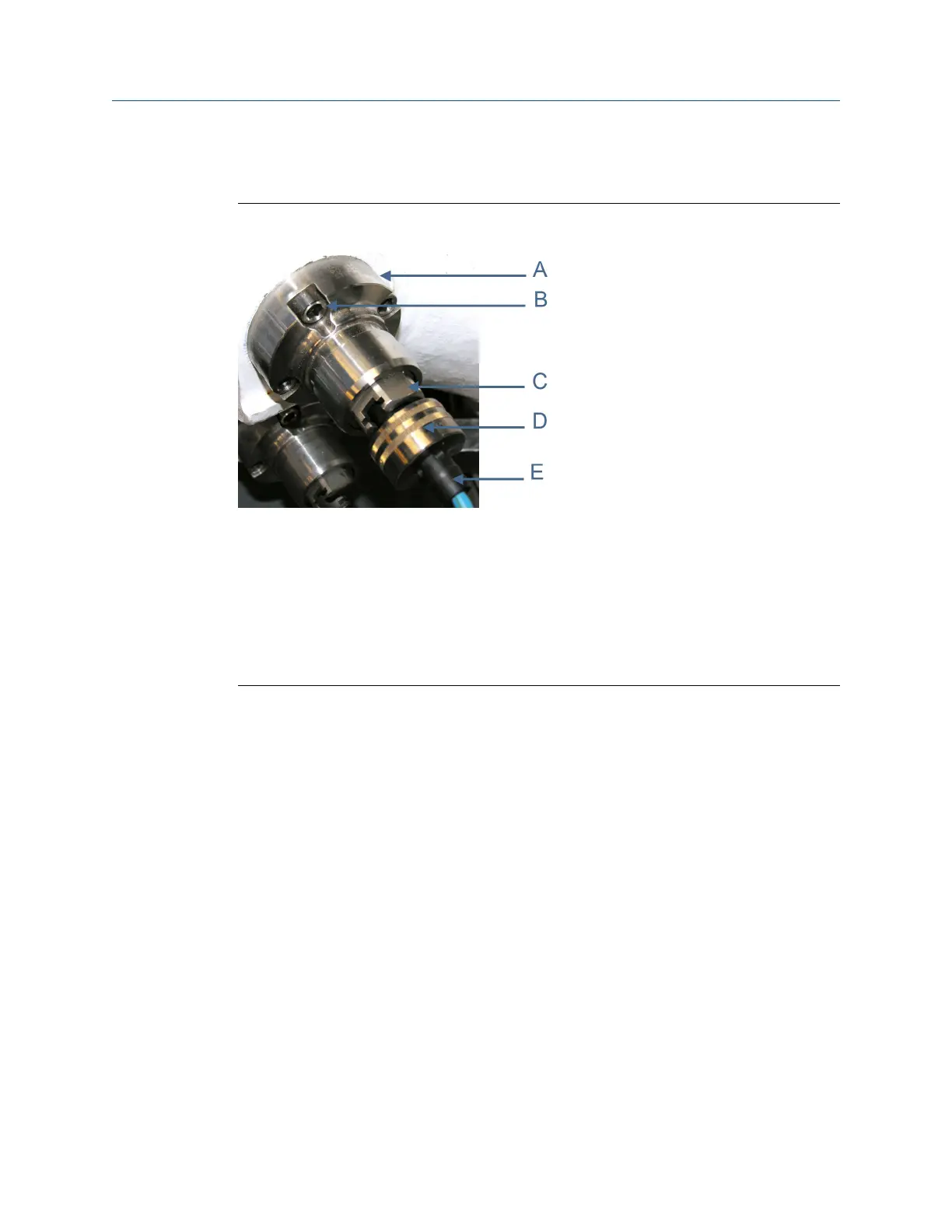
T-slot transducer mount and holderFigure 1-1:
A. Transducer mount
B. Captive screws
C. T-slot transducer holder
D. Cable nut
E. Chordset
Procedure
1. Slowly vent all line pressure on the 3410 Series Gas Ultrasonic Meter to atmosphere.
2. Disconnect transducer cable from the transducer holder.
3. If installed, remove the mount cover by loosening the two mount cover captive
screws.
4. Loosen the T-Slot transducer assembly with a 1 1/4 inch (32 mm) socket. Carefully
remove the T-Slot transducer assembly.
5. Place a label on the transducer assembly to marks its location (i.e., Model 3414-A1,
A2, B1, B2, C1, C2, D1, or D2; 3412-A1, A2, B1, B2; or 3411-A). Port locations are
marked on the transducer cable as well as on cast meter housings.
6. Inspect the transducer mount threads and ensure they are clean and free of debris.
7. Apply a small amount of Nickel antiseize compound (P/N 3-9960-134) to the
threads of the Hydrotest plug (P/N 1-360-01-212) from kit (P/N 1-360-01-220) and
install it into the mount. JuniorSonic kit part numbers are listed below.
• JuniorSonic
™
SP Field Hydrotest Kit (P/N 1-360-01-221)
• JuniorSonic
™
DP Field Hydrotest Kit (P/N 1-360-01-222)
Maintenance
Maintenance and Troubleshooting manual 3

 Loading...


